Dual Pixel Pitch Imaging Array with Extended Dynamic Range

a dynamic range and imaging array technology, applied in the field of dual pixel pitch imaging arrays, can solve the problems of no detector technology, complex sensor design, and added complexity to the external chip control electronics and the camera mechanical housing, and achieve the effect of expanding the dynamic range of the focal plane imaging array

Inactive Publication Date: 2013-03-28
SCOTT BASIL HENRY +2
View PDF8 Cites 48 Cited by
  • Summary
  • Abstract
  • Description
  • Claims
  • Application Information

AI Technical Summary

Benefits of technology

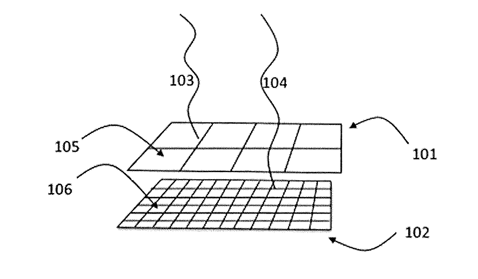
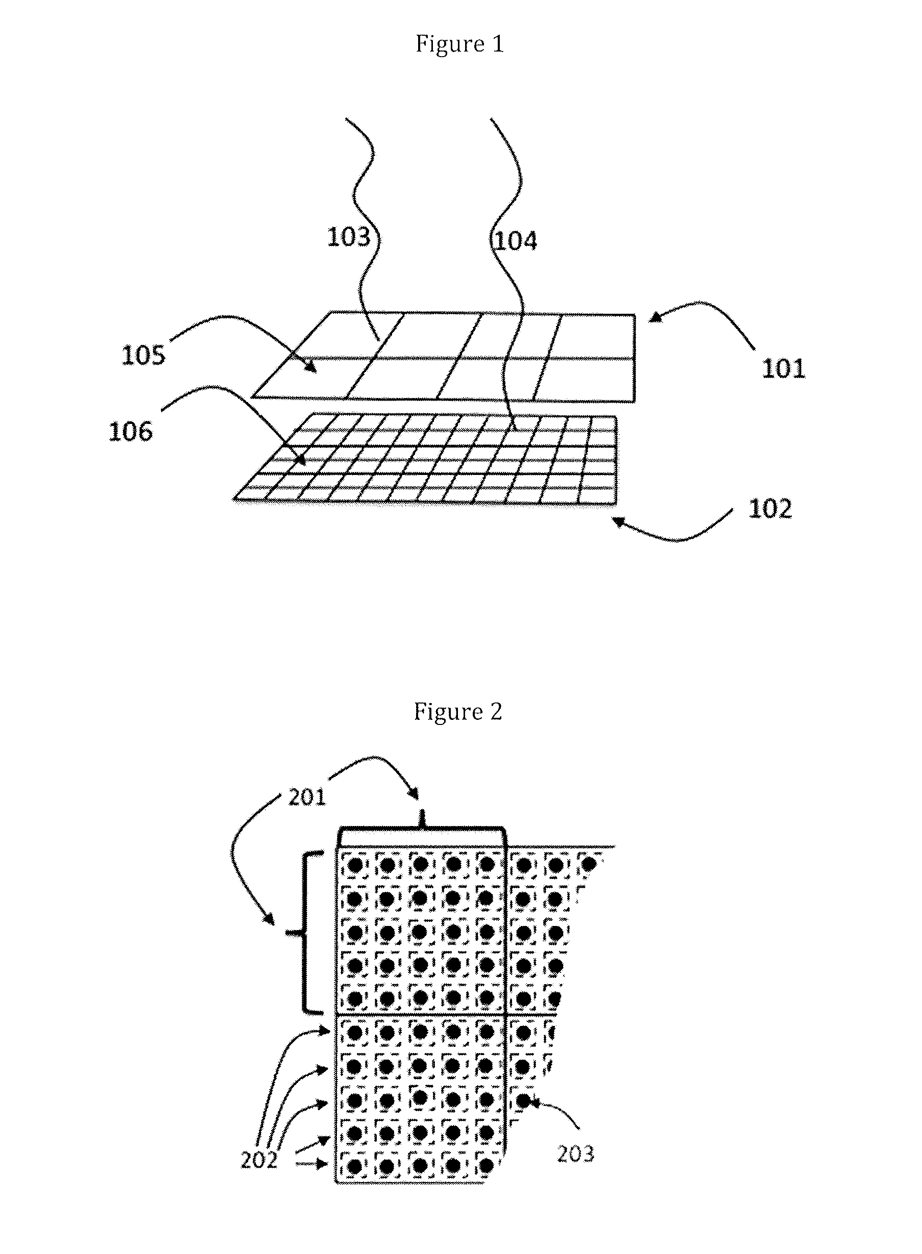
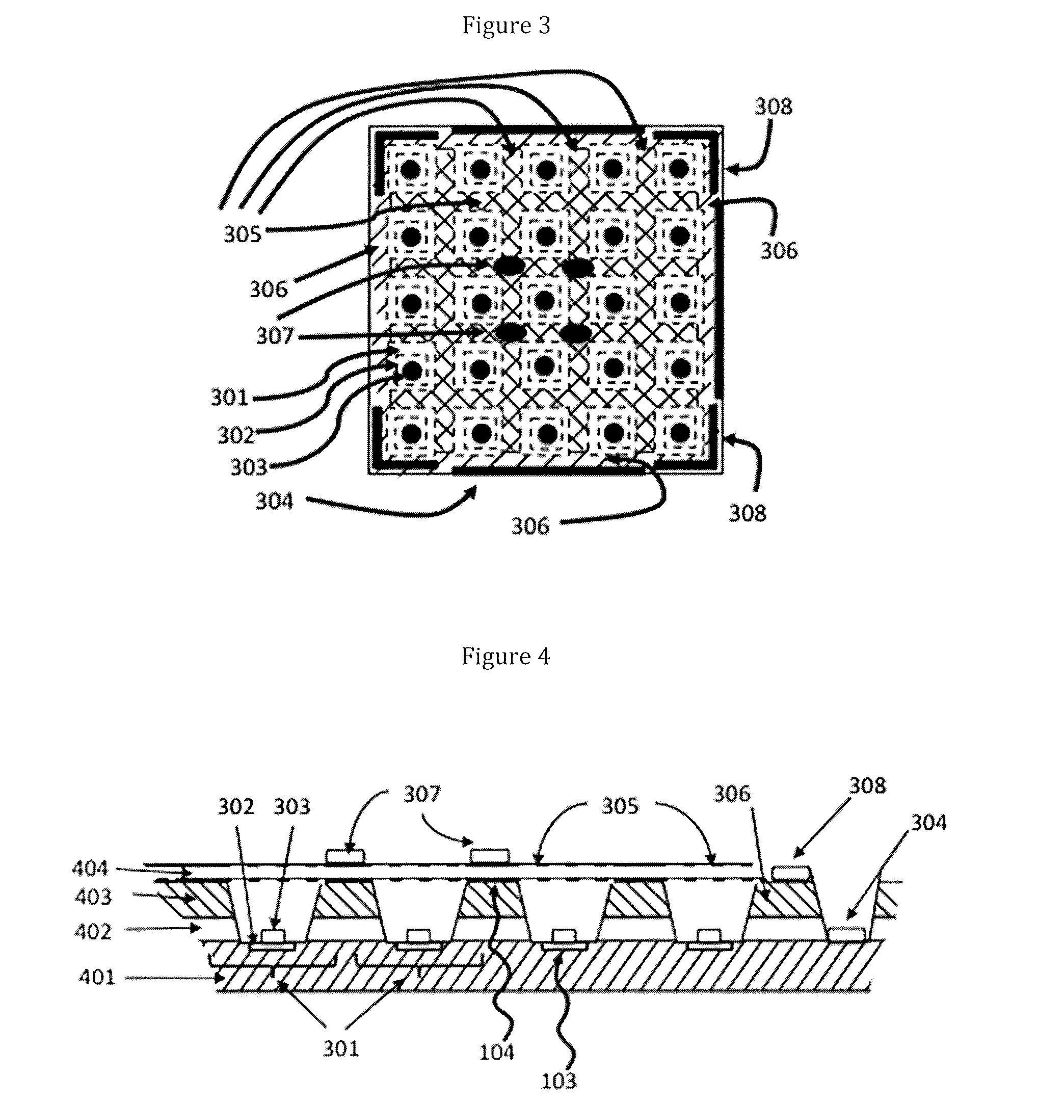
[0026]The above and other objects are preferably achieved by a focal plane imaging array having a dynamic range, comprising: a detector with a large pixel array having a plurality of large pixels, each of the large pixels having a large pixel area and a large pixel signal contact, to create a first signal that travels to the large pixel signal contact, and a small pixel array having a plurality of small pixels, each of the small pixels having a small pixel area and a small pixel signal contact, to create a second signal that travels to the small pixel signal contacts, wherein the plurality of small pixels is greater than the plurality of large pixels, wherein the large pixel array and the small pixel array are aligned and vertically stacked on a monolithic semiconductor substrate; a readout integrated circuit operably interconnected to the large pixel signal contacts and the small pixel signal contacts; and a clock operably connected to the large pixel signal contacts and the small pixel signal contacts to read the first signals at a first clock rate having a first integration time and a first reset time, and to read the second signals at a second clock rate having a second integration time and a second reset time. The first clock rate is preferably faster than the second clock rate, and the reading of the first signals at the first clock rate, and the second signals at the second clock rate, extends the dynamic range of the focal plane imaging array.
[0033]Ultimately, the reading of the first signals at the first changed integration time, and the second signals at the second changed integration time and the second re-changed integration time, extends the dynamic range of the focal plane array.
[0041]The above and other objects are also preferably achieved by a process for using a focal plane imaging array having a background brightness and a detector operably connected to a readout circuit having a large pixel array with a plurality of large pixels, each of the large pixels having a large pixel area and a large pixel signal contact, to absorb a first wavelength, and a small pixel array having a plurality of small pixels, each of the small pixels having a small pixel area and a small pixel signal contact, to absorb a second wavelength, wherein said plurality of small pixels is greater than said plurality of large pixels, and wherein the large pixel array and the small pixel array are aligned and vertically stacked on a monolithic semiconductor substrate, comprising: illuminating the large pixel array and small pixel array with an infrared light source to create a first signal that travels to the large pixel signal contacts, and a second signal that travels to the small pixel signal contacts; clocking the first signal at a first clock rate having a first integration time and a first reset time, and the second signal at a second clock rate having a second integration time and a second reset time, wherein the first clock rate is faster than the second clock rate; and shortening the first integration time if the first signal saturates the large pixels between the first rest times, and reducing the second integration time if the second signal saturates the small pixels between the second reset times. This process achieves an extended dynamic range and better clutter rejection for the focal plane array.

Problems solved by technology

For military-use or security-use systems, multiple competing requirements complicate sensor design, especially infrared (IR) sensor design.
No detector technology exists that meets these goals.
This achieves a 2× to 8× speed improvement, but adds complexity to the external chip control electronics and to the camera mechanical housing, which is typically a cryogenic dewar flask.
Current IR sensors achieve a dynamic range of less than 20 thousand, and this often presents a problem in real applications.
However, both HDR and the sigma-delta approach result in performance tradeoffs.
Clutter rejection methods have employed two-color radiometric techniques, which are highly effective, but clutter in the IR bands remains a difficult problem.
However, these techniques are limited by how precisely the temperature is determined.
They are also limited because some benign events have similar temperatures to threatening ones.
For example, it would be difficult to distinguish a gunshot from an automobile backfire using temperature alone.
Achieving the very large dynamic range of operation required for military / security systems, combined with flexible operation, while providing new types of data for clutter rejection is a very difficult challenge.
Simply extending current design approaches is not the answer.
If a sensor is saturated, it is temporarily blinded.

Method used


Image

  • Dual Pixel Pitch Imaging Array with Extended Dynamic Range
  • Dual Pixel Pitch Imaging Array with Extended Dynamic Range
  • Dual Pixel Pitch Imaging Array with Extended Dynamic Range

Examples


case 1

[0131]In the preferred implementation described above, the present invention uses six clock signals and four logical bits to indicate the gain state, as indicated in FIGS. 12 and 15. In alternate implementations, fewer clock signals and fewer gain state bits may be desirable. Practical cases of interest include:[0132] Dual fixed clock signals, one fast for large pixels and one slow for small pixels; and[0133]Case 2: Dual clock signals with one small pixel clock variation so that only φS1, φS2, and φL1 as shown in FIG. 12 are used.

While not offering the full range of operation of the preferred implementation, each of these practical implementations still offers advantages over current focal plane arrays.

[0134]For case 1, the dual array can be operated so as to offset the responsivity range of the large and small pixels, resulting in a large dynamic range through their combined operation. As a specific example, 80 micron large pixels with an electronic gain of 20 nV / electron, an integ...


PUM


Abstract

An integrated focal plane provides two co-aligned, overlapping pixel arrays in two formats, one with large pixels and low pixel count, the other with small pixels and high pixel count. Typically, the large pixels are 10 to 100 times larger in area than the small pixels. The dual arrays are disposed in a single detector substrate flip-chip bonded to a single readout circuit. They are sensitive to two infrared colors, one shorter and one longer wavelength band. The dual array focal plane concurrently provides two distinct pixel instantaneous fields of view within the same overall field of view as well as simultaneous fast and slow frame rates. The dual frame rates allow for combined fast sensing with sensitive imaging. Differing spatial and temporal data enables enhanced image processing for improved clutter rejection and detection performance. Differing gains combined with the dual frame rates provide an extended dynamic range.

Description

[0001]This application claims the priority of U.S. provisional patent application No. 61 / 538,064 filed Sep. 22, 2011.FIELD OF THE INVENTION[0002]The present invention generally relates to camera focal plane imaging arrays. More specifically, the invention relates to a camera focal plane imaging array that is optimized to meet competing performance requirements for military or security sensing systems.BACKGROUND OF THE INVENTION[0003]For military-use or security-use systems, multiple competing requirements complicate sensor design, especially infrared (IR) sensor design. Quantitatively, an ideal military / security system needs a fast sensing mode that operates at maximum rates of 1500 to 5000 frames per second, combined with a slow, staring capability that can match the sensitivity of a high-quality 30 frame per second sensor. It needs resolution suitable for fine-grained images, and a dynamic range (the difference between the darkest signal that can be measured and the brightest sign...

Claims


Application Information

Patent Timeline
Patent Type & Authority Applications(United States)
IPC IPC(8): H04N5/33
CPCH04N5/332H04N5/3696H04N5/343H03K5/125H04N23/11H04N25/42H04N25/702
Inventor SCOTT, BASIL HENRY
Owner SCOTT BASIL HENRY
Why Eureka
Try Eureka