Bone anchoring assembly

Inactive Publication Date: 2013-03-28
BIEDERMANN TECH GMBH & CO KG
16 Cites 10 Cited by

AI-Extracted Technical Summary

Problems solved by technology

With such engagement structures there is a risk of weakening the rod, if the rod diameter is small.
However, there is a need for the use of bone anchoring assemblies of the type using a...

Method used

As can be seen in particularly in FIGS 4c, 4d, the arrangement of the pin fixation seen in the direction perpendicular to the longitudinal axis of the rod 8 is a three-point fixation, which is particula...

Benefits of technology

[0013]Mechanical stops are provided preventing a penetration of the clampin...

Abstract

A bone anchoring assembly for dynamic stabilization is provided. The bone anchoring assembly includes a bone anchoring element having a head and a shank to be anchored in a bone or a vertebra, a receiving part for receiving a rod, a pressure element and a monolithic locking element. The rod (8) includes a flexible section which is made at least partly of a polymer material. The receiving part comprises a first channel with an approximately U-shaped cross-section with two free legs. Furthermore, the locking element directly cooperates with the legs to simultaneously secure the rod in the first channel (58) and exert a pressure on the pressure element that exerts pressure onto the head of the bone anchoring element to lock the angular position of the bone anchoring element relative to the receiving part. A first pin-shaped projection is provided at the locking element which comes into contact with the flexible section of the rod when tightening the locking element.

Application Domain

Technology Topic

Image

  • Bone anchoring assembly
  • Bone anchoring assembly
  • Bone anchoring assembly

Examples

  • Experimental program(1)

Example

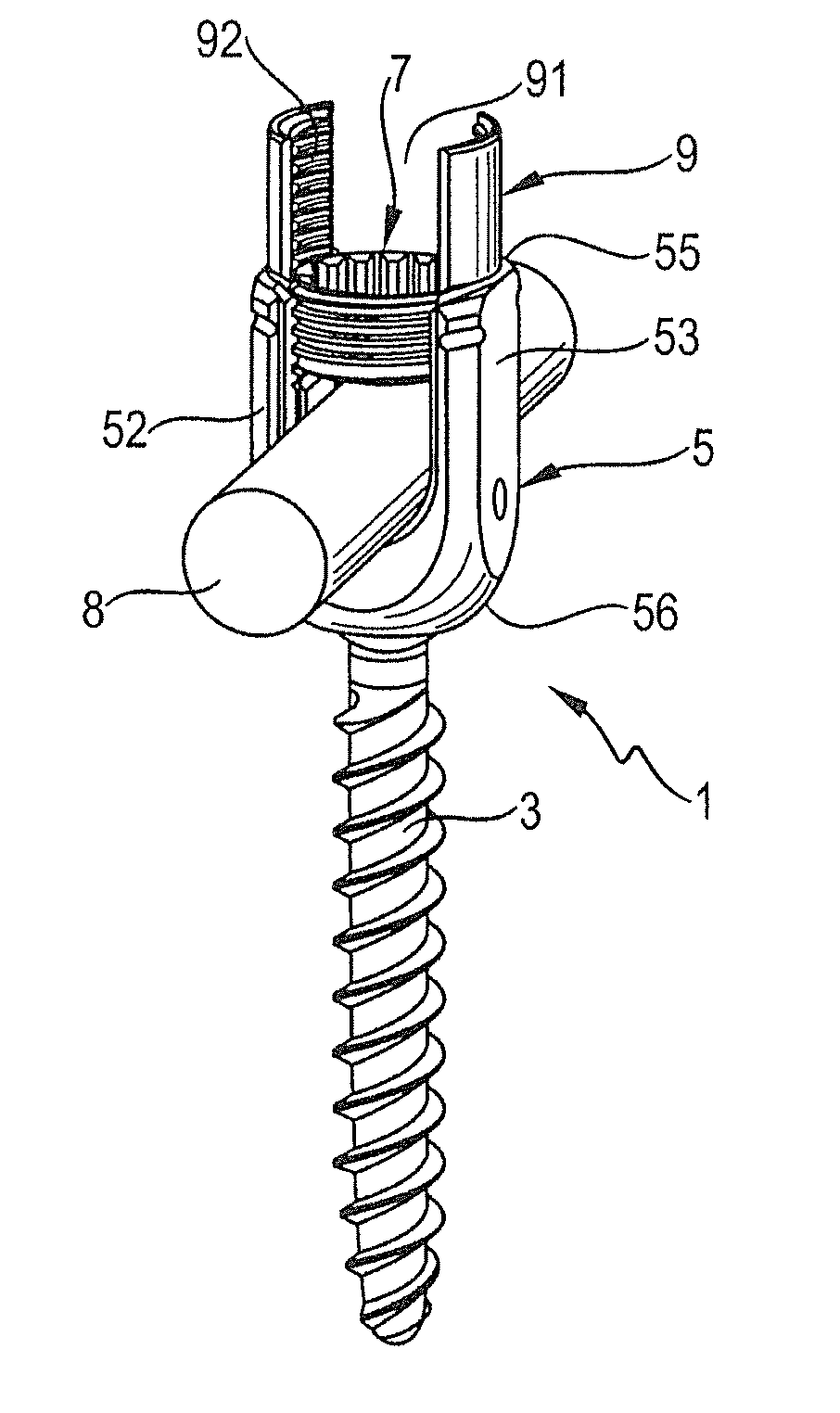
[0031]A bone anchoring assembly comprises one or more (not shown) bone anchoring devices 1 and a rod 8, wherein the bone anchoring devices 1 can be interconnected via the rod 8.
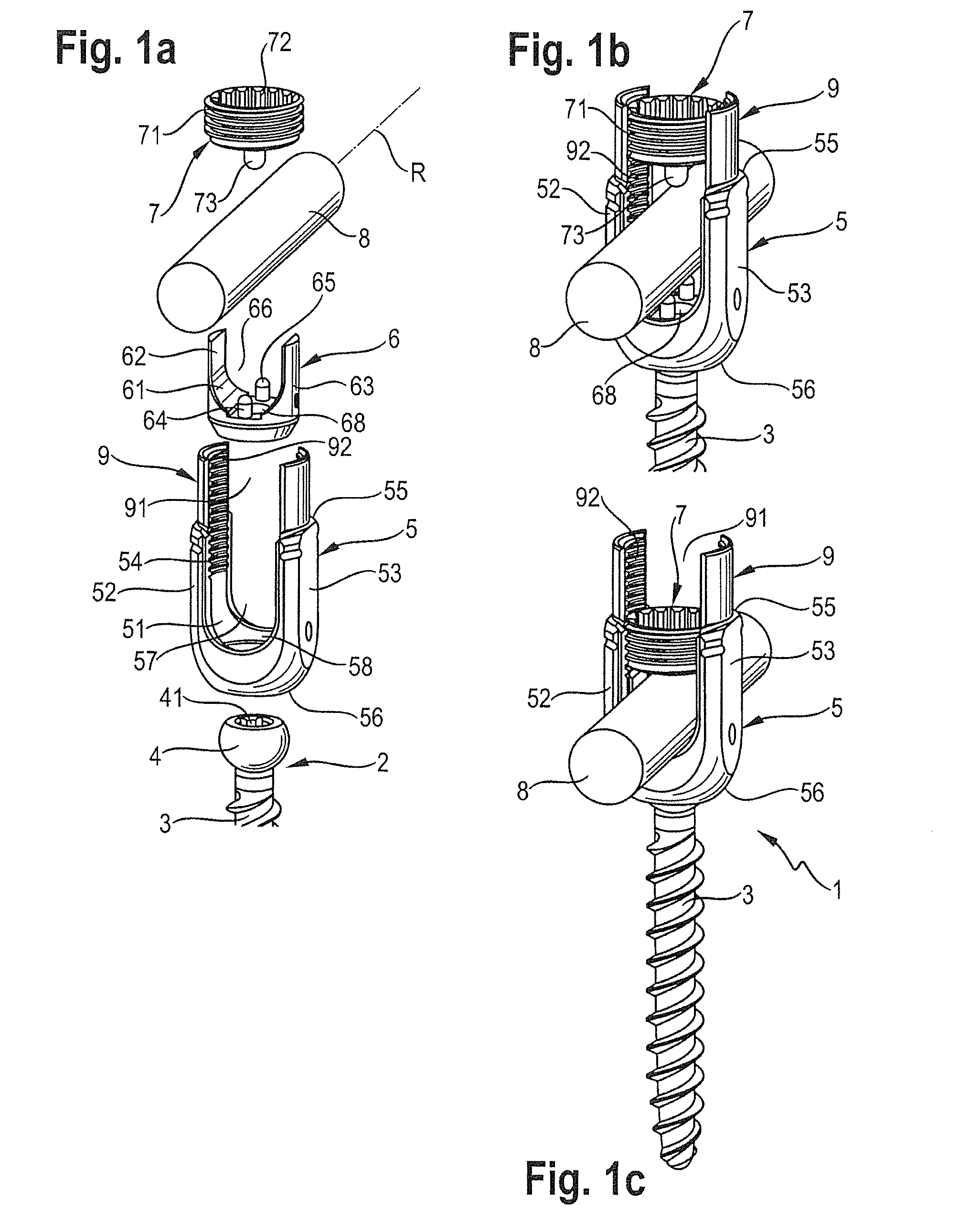
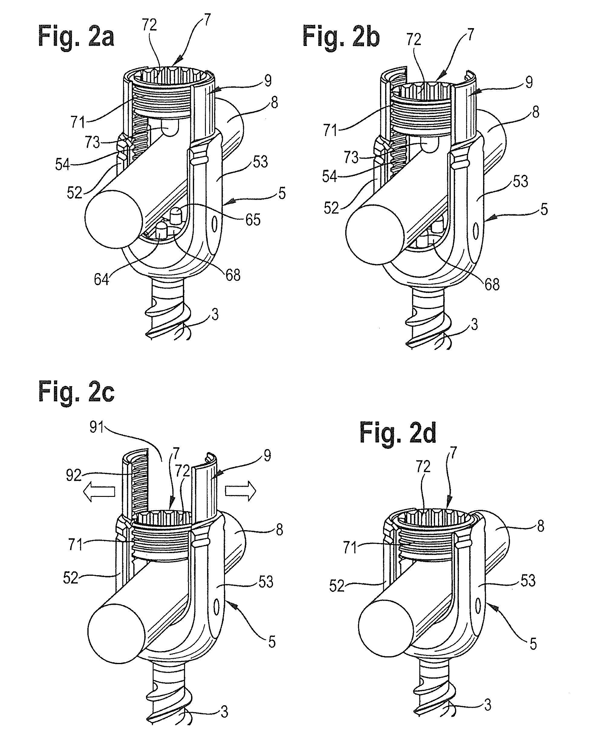
[0032]As shown in FIGS. 1a to 4d, the bone anchoring device 1 comprises a bone anchoring element 2 in the form of a polyaxial bone screw having a shank 3 with a bone thread and a tip at one end and a head 4 having an engagement structure 41 at the opposite end. The bone anchoring device 1 furthermore comprises a receiving part 5, a pressure element 6, a locking element 7 and a tube-shaped extension 9 integrally formed with the receiving part 5.
[0033]The receiving part 5 is substantially cylindrical and comprises a first end 55, a second end 56 and a coaxial bore 57 extending from the first end 55 to the second end 56 and tapering in an area near the second end 56 such that, as shown in FIG. 3a, the head 4 of the bone anchoring element 2 is pivotably held in the receiving part 5 at the second end 56. Furthermore, the receiving part 5 comprises a U-shaped recess 51 extending from the first end 55 in the direction of the second end 56. By means of the U-shaped recess 51 two free legs 52, 53 are formed which comprise an internal thread 54, wherein a channel 58 is formed.
[0034]The pressure element 6 is substantially cylindrical and dimensioned such that it can be moved within the bore 57 of the receiving part 5. The pressure element 6 has a coaxial bore 66 extending through the pressure element 6 and allowing a screwing-in tool to be guided therethrough for screwing the bone anchoring element 2 into a bone. The pressure element 6 further comprises a spherical recess 67, which is adapted to receive the spherical head 4 of the bone anchoring element 2. Further, the pressure element 6 comprises a substantially U-shaped recess 61 extending from its free end in the direction of the spherical recess 67. By means of the U-shaped recess 61 two free legs 62, 63 are formed, which form the lateral walls of a channel 68 for receiving the rod 8. On the bottom of the channel 68 two pin-shaped projections 64, 65 or pins 64, 65 are provided which are located preferably at both ends of the channel 68. The pins 64, 65 are substantially cylindrical and their free ends are rounded, preferably semi-spherical. More specifically, the pins 64, 65 are longitudinal rod-shaped pins with rounded free ends. However, they can have any shape as long as the uppermost portions are rounded as described. The uppermost portions of the pins 64, 65 are located on a line, which is parallel to the longitudinal axis R of the rod 8.
[0035]As shown in particular in FIG. 3c the pressure element 6 is sized in such a way that the legs 62, 63 of the pressure element 6 extend slightly above the surface of the rod 8 when the rod 8 is inserted into the channel 68 and the pins 64, 65 are immersed into the surface of the rod 8. The upper edge of the legs 62, 63 of the pressure element 6 form a stop for the main body of the locking element 7.
[0036]The locking element 7 is a single part locking element and can be formed as an inner screw and comprises an outer thread 71, an engagement structure 72 for engagement with a tool and a coaxial pin 73 for pressing onto the rod 8. The pin 73 is preferably cylindrical with a semi-spherical free end, more specifically, the pin 73 is a longitudinal rod-shaped pin with a rounded free end and corresponds in its dimension substantially to the dimensions of the pins 64, 65 of the pressure element 6.
[0037]The bone anchoring element 2, the receiving part 5, the pressure element 6, the locking element 7 and also the tube-shaped extension 9 can be made of a biocompatible material, such as, for example, titanium or stainless steel or another biocompatible material, for example polyether ether ketone (PEEK).
[0038]The rod 8 is made at least in part of a flexible biocompatible material, preferably of a plastic material and in particular of an elastomer material. Such a material can be based on, for example, polycarbonate-polyurethane or polycarbonate-urethane (PCU). However, other materials are also applicable, for example styrene-block-isobutylene-block-styrene (SIBS) and other elastomers. The rod 8 need not be made totally of one single material, but can comprise several materials and inner structures and/or sections with different flexibility and/or rigidity. The flexible section is the section which is to be clamped in the receiving part 5. The diameter of the rod 8 can be any of the usual smaller diameters of rods for stabilization of the spine, in particular diameters from 4.5 mm to 9 mm.
[0039]The coaxial tube-shaped extension 9 has a slot 91 for inserting the rod 8 and an internal thread 92 which cooperates with the inner thread 54 of the receiving part 5. The extension 9 is used for minimally invasive surgery and can be broken away after tightening the locking element 7, preferably manually. For breaking away the tube-shaped extension 9 in an easy way, a predetermined breaking point, i.e., a material weakness formed by a groove between the receiving part 5 and the tube-shaped extension 9 for example can be provided.
[0040]In use, as can be seen from FIGS. 2a to 4d, firstly at least two bone anchoring devices 1 are screwed into adjacent vertebrae, for example into the pedicles. At least one of the bone anchoring devices 1 is formed according to the invention. Thereafter, the rod 8 is inserted into the receiving part 5 and is fixed. The procedure of fixation is now explained with reference to FIGS. 2a to 4d. As shown in FIGS. 2a, 3a, 4a, in a first configuration the locking element 7 is screwed into the tube-shaped extension 9. The rod 8 is inserted into the channel 68 until it rests onto the pins 64, 65 of the pressure element 6 or on the pin 73 of the locking element 7. As can be seen from FIGS. 2b, 2c, 3b, 3c, 4b, 4c, when the locking element 7 is screwed in completely between the legs of the tube-shaped extension 9 and then between the legs 52, 53 of the receiving part 5, the pins 64, 65 are pressing into the surface of the rod 8 until they are fully immersed in the surface of the rod 8 due to the local flow of the material of the rod 8, which leads to a local elastic and/or plastic deformation of the rod 8. The engagement of the pins 64, 65 with the rod 8 is such that the integral structure of the rod 8 is not violated.
[0041]The pin 73 of the locking element 7 is also fully immersed in the surface of the rod 8 due to the local flow of the material of the rod 8 which leads to a local elastic and/or plastic deformation of the rod 8.
[0042]Due to the mechanical stop by the upper edge of the pressure element 6, the movement of the locking element 7 is restricted.
[0043]After screwing in the full immersion of the pins 64, 65, 73, the tube-shaped extension 9 is broken away via the predetermined breaking point after tightening the locking element 7 as indicated in FIGS. 2c, 3c by the arrows.
[0044]The dimension of the pins 64, 65, 73, in particular their height, the diameter and the radius of the free end portion is designed such that under a given pressure force which is limited by the stop described above, the pins 64, 65, 73 do not violate the integral structure of the rod 8.
[0045]As can be seen in particular in FIGS. 4c, 4d, the arrangement of the pin fixation seen in the direction perpendicular to the longitudinal axis of the rod 8 is a three-point fixation, which is particularly safe. That means, there is no clamping on locations which are exactly on opposite sides of the rod 8 which may cause the danger of violating the integral structure of the rod 8 at the clamping site.
[0046]Several modifications are conceivable. For example, the number of pins in the bottom of the channel of the pressure element or also the number of pins of the locking element may vary. In some cases more than two pins might be of advantage referring to the pressure element. The shape of the pins can also vary. However, the height of the pins and the radius of the uppermost rounded portion must be designed such that there is no violation of the integral structure of the rod, while simultaneously providing safe fixation.
[0047]All other kinds of polyaxial bone anchoring assemblies known may be conceivable which can be modified so as to have the pins described above. For example, a polyaxial screw, where the bone anchor is inserted from below, a so-called bottom loader, may be also used.

PUM

no PUM

Description & Claims & Application Information

We can also present the details of the Description, Claims and Application information to help users get a comprehensive understanding of the technical details of the patent, such as background art, summary of invention, brief description of drawings, description of embodiments, and other original content. On the other hand, users can also determine the specific scope of protection of the technology through the list of claims; as well as understand the changes in the life cycle of the technology with the presentation of the patent timeline. Login to view more.

Similar technology patents

Classification and recommendation of technical efficacy words

Why Eureka
Try Eureka