Electron linac for medical isotope production with improved energy efficiency and isotope recovery

a radioisotope and electron linac technology, applied in accelerators, chemical to radiation conversion, electrical instruments, etc., can solve the problems of large operating burden to control the heu and insufficient quantity of isotopes to meet the demand for medical applications, and the use of highly enriched 235/sup>u (heu),

Active Publication Date: 2013-04-04
UCHICAGO ARGONNE LLC
View PDF3 Cites 18 Cited by
  • Summary
  • Abstract
  • Description
  • Claims
  • Application Information

AI Technical Summary

Benefits of technology

[0014]In accordance with features of the invention, using the ERL reduces the effective operating voltage of the energy recovery linear accelerator, improves the efficiency of the machine by reducing the external power requirement for a selected electron beam power, and improves the thermal management of the isotope target and electron-to-x-ray converter.
[0016]In accordance with features of the invention, in the one embodiment with the recycled beam lattice a simple isotope target design is enabled. The target includes a single γ-ray converter and a thin isotope target. The single γ-ray converter has a thickness that is determined by the energy acceptance for the accelerating structure. The converter is just thick enough to create gamma radiation that is required for photo-fission of the target.
[0017]In accordance with features of the invention, in one embodiment the ERL includes an electron injector, an accelerating linac structure, and a target. The linac is followed by a second linac structure that decelerates the electron beam to recover the RF power. The RF is then transmitted to the accelerating linac. An advantage of this configuration is that the beam return lattice is eliminated.
[0018]In accordance with features of the invention, in one embodiment the ERL includes a pair of electron guns and a pair of accelerating linacs that are in-line, with one linac is injecting spent beam into an opposite accelerating structure; and a target and refocusing magnets to refocus the spent beam are located between the two linacs. A first advantage of this configuration is that the spent beam of one linac powers the RF for the other linac, and the accelerator lattice does not require a return lattice. Another advantage is that there is no high energy-low energy merge or separation, as needed for recycling ERLs. Therefore, the spent beam can be drawn down to very low energy which increases the energy efficiency. Yet another advantage is that there are two electron beams bombarding the target, so the isotope production is increased by a factor of two. The target for this configuration is special. The target is sandwiched between two γ-ray converters. The configuration requires refocusing elements on both sides of the target.

Problems solved by technology

However, the quantity of isotopes is insufficient to meet today's demand for medical applications.
A major drawback of reactors is the use of highly enriched 235U (HEU).
There is a significant operating burden to control the HEU to prevent nuclear proliferation.
Until recently the cost of building a reactor could not be recovered simply by commercialization of medical isotopes.
The proton / heavy ion linacs and cyclotrons are also expensive, complex systems that require significant capital investment, operating cost, and regularity oversight.
Extended operation of high-current proton accelerators can lead to the accelerators themselves becoming radioactive, through interaction of the accelerator with scattered, or “lost,” high-energy protons.
Protons are very effective in producing radio-isotopes, but the linacs are expensive, and therefore, limited in number.
The state-of-the-craft linacs have several technical limits that prevent increasing the isotope production for a given electron linac.
For example, the existing technology limits how much additional beam power can be added to increase capacity.
The ability to cool the converter / target becomes increasingly unmanageable.
However, this increases the length of the linac, which increases cost; the additional component count also adds costs and reduces reliability.
The interaction generates a high intensity, coherent photon source but is inefficient, converting ˜1% of the electron beam power into photons.

Method used


Image

  • Electron linac for medical isotope production with improved energy efficiency and isotope recovery
  • Electron linac for medical isotope production with improved energy efficiency and isotope recovery
  • Electron linac for medical isotope production with improved energy efficiency and isotope recovery

Examples


Embodiment Construction

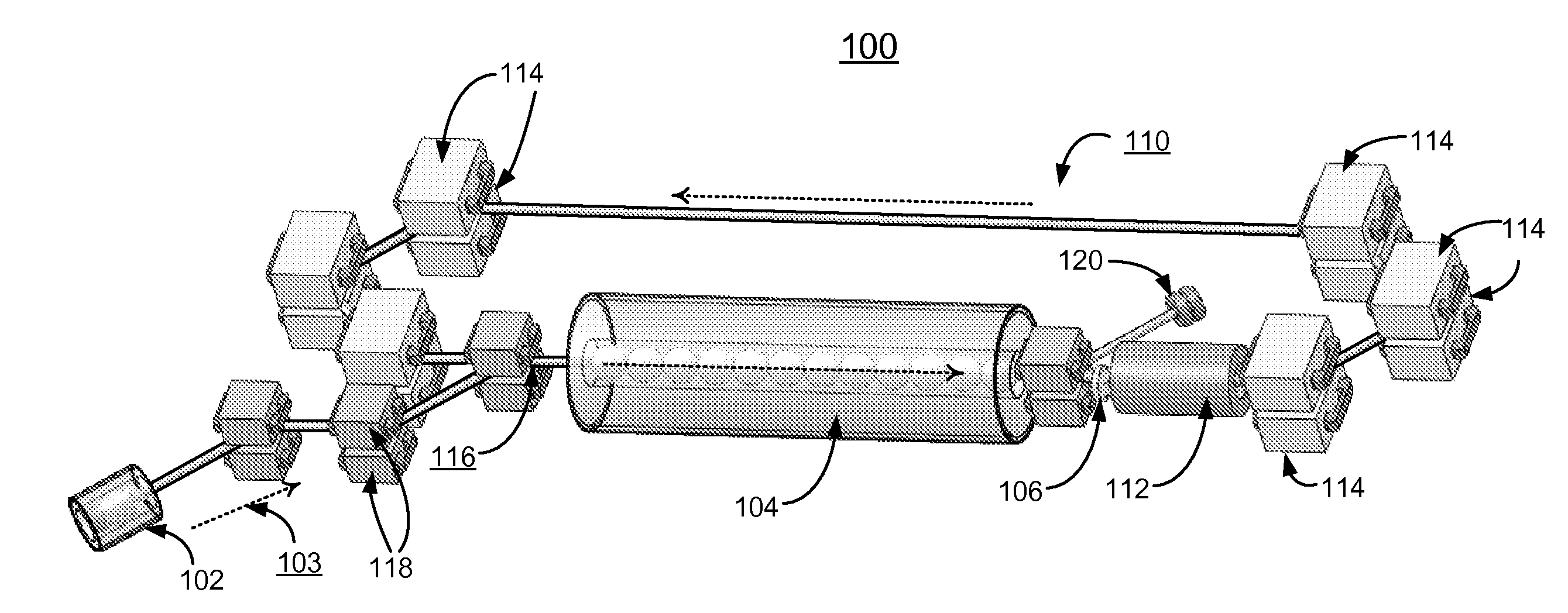
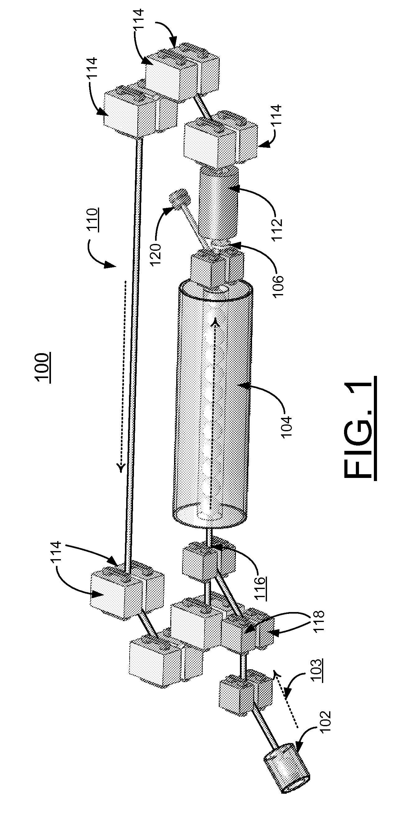
[0027]In accordance with features of the invention, a method and energy recovery linear accelerator are provided for producing radio-isotopes and recovering the isotopes in a continuous process. The energy recovery linac or isotope linac is a linac with an electron beam being transmitted through an isotope-producing target. The electron beam energy is recollected and re-injected into an accelerating structure.

[0028]In accordance with features of the invention, the isotope linac of the invention uses an ERL technology in which the electron beam that is transmitted through the target is recollected and re-injected into the accelerating structure. The present invention is a first use of ERLs for isotope production. One of the invention advantages is that the recollected beam transfers beam power to the injected electron beam, and reduces the amount of externally supplied RF power required to accelerate the electrons to energy. Therefore, the ERL isotope linac reduces the external RF po...


PUM


Abstract

A method and isotope linac system are provided for producing radio-isotopes and for recovering isotopes. The isotope linac is an energy recovery linac (ERL) with an electron beam being transmitted through an isotope-producing target. The electron beam energy is recollected and re-injected into an accelerating structure. The ERL provides improved efficiency with reduced power requirements and provides improved thermal management of an isotope target and an electron-to-x-ray converter.

Description

CONTRACTUAL ORIGIN OF THE INVENTION[0001]The United States Government has rights in this invention pursuant to Contract No. DE-AC02-06CH11357 between the United States Government and UChicago Argonne, LLC representing Argonne National Laboratory.FIELD OF THE INVENTION[0002]The present invention relates generally to the field of medical radio-isotope producing such as 99Mo, 67Cu and others, and more particularly, relates to a method and an improved electron linear accelerator for producing radio-isotopes; and more specifically, relates to an energy recovery linear accelerator used to produce radio-isotopes and to recover the isotopes in a continuous process.DESCRIPTION OF THE RELATED ARTIsotope Production[0003]Radio-isotopes are used extensively for imaging and treatment of a variety of medical problems. Radio-isotopes can occur naturally due to radioactive decay of heavy atoms, such as 235U or 239Pu. However, the quantity of isotopes is insufficient to meet today's demand for medica...

Claims


Application Information

Patent Timeline
Patent Type & Authority Applications(United States)
IPC IPC(8): G21G1/10H05H9/00
CPCG21G1/10H05H7/02H05H9/00
Inventor NOONAN, JOHNWALTERS, DEANVIRGO, MATTLEWELLEN, JOHN
Owner UCHICAGO ARGONNE LLC
Why Eureka
Try Eureka