starter

a technology of starters and starters, applied in the field of starters, can solve the problems of difficult to secure high durability of starters, relative inclination between male and female splines, adhesion between tooth surfaces, etc., and achieve the effect of suppressing wear of the two surfaces, reducing the number of times the starter starts the engine of the vehicle, and reducing the number of times the starter starts the engin

Inactive Publication Date: 2013-04-11
DENSO CORP
View PDF5 Cites 5 Cited by
  • Summary
  • Abstract
  • Description
  • Claims
  • Application Information

AI Technical Summary

Benefits of technology

[0014]Consequently, without relative rotation between the output shaft and the pinion tube, it is possible to reliably suppress wear of the outer surface of the output shaft and the inner surface of the pinion tube even when the vehicle is equipped with an ISS and thus the number of times the starter starts the engine of the vehicle is dramatically increased. Therefore, it is unnecessary to provide a large radial clearance between the outer surface of the output shaft and the inner surface of the pinion tube for the purpose of suppressing wear of the two surfaces. In other words, it is possible to minimize the radial clearance between the outer surface of the output shaft and the inner surface of the pinion tube. As a result, with the minimized radial clearance, it is also possible to minimize relative inclination between the output shaft and the pinion tube.
[0015]Further, with the minimized relative inclination between the output shaft and the pinion tube, it is possible to reliably prevent local increase in contact pressure between the male helical splines of the output shaft and the female helical splines of the pinion tube, thereby reliably preventing adhesion between the tooth surfaces of the male and female helical splines. As a result, it is possible to secure high durability (or a long service life) of the starter.
[0016]Furthermore, without relative rotation between the output shaft and the pinion tube, it is unnecessary to provide a bearing between the outer surface of the output shaft and the inner surface of the pinion tube. Consequently, without having to provide a bearing between the outer surface of the output shaft and the inner surface of the pinion tube, it is possible to minimize the parts count and thus the manufacturing cost of the starter. Moreover, without a bearing provided between the outer surface of the output shaft and the inner surface of the pinion tube, it is possible to more effectively minimize the radial clearance therebetween.
[0017]In addition, even if a bearing was provided between the outer surface of the output shaft and the inner surface of the pinion tube, it would be possible to reliably prevent seizure of the bearing because relative rotation between the output shaft and the pinion tube would be restricted by the relative rotation restricting means when the clutch is in the overrun state.

Problems solved by technology

Consequently, adhesion between the tooth surfaces of the male and female splines may occur, thereby making it difficult to secure high durability of the starter.
Consequently, the rotation of the pinion 140 will be suddenly stopped, inducing an excessive mechanical shock at the spline engagement portion and thereby causing relative inclination between the male and female splines.
As a result, with the relative inclination between the male and female splines, an excessive contact pressure will be generated between the male and female splines due to local contact therebetween, thereby causing adhesion between the tooth surfaces of the male and female splines.
At this time, however, relative rotation between the output shaft and the pinion tube is restricted by the relative rotation restricting means, unlike in the conventional starter as disclosed in Japanese Patent Application Publication No. 2006-177168.
Furthermore, without relative rotation between the output shaft and the pinion tube, it is unnecessary to provide a bearing between the outer surface of the output shaft and the inner surface of the pinion tube.

Method used


Image

  • starter
  • starter
  • starter

Examples


Embodiment Construction

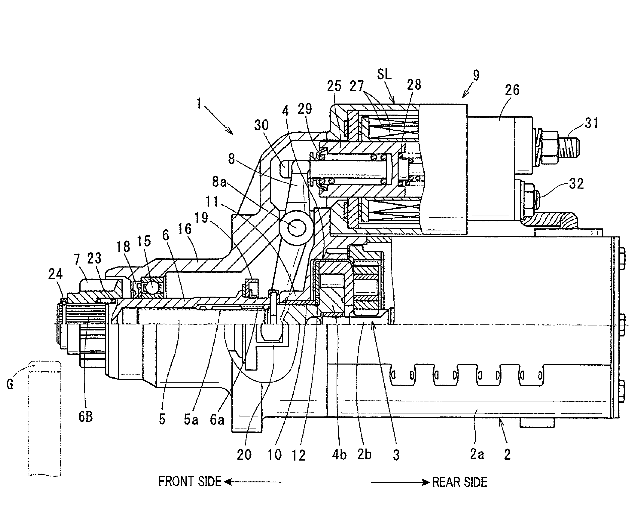
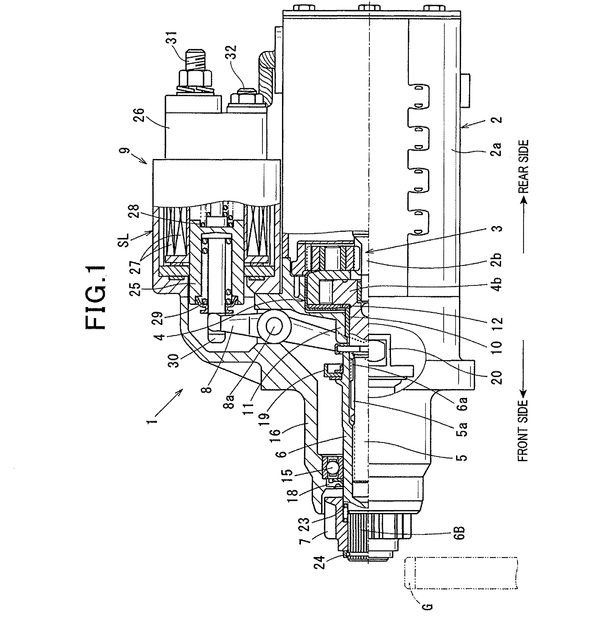
[0028]FIG. 1 shows the overall structure of a starter 1 according to an exemplary embodiment. The starter 1 is designed to start an internal combustion engine (not shown) of a motor vehicle.

[0029]As shown in FIG. 1, the starter 1 includes: a motor 2 that generates torque; a speed reducer 3 that reduces the rotational speed of the motor 2; a clutch 4; an output shaft 5 that is mechanically connected to the output side of the speed reducer 3 via the clutch 4; a pinion tube 6 that is helical-spline-fitted to the outer periphery of the output shaft 5; a pinion 7 that is fitted on a non-motor-side end portion (i.e., a left end portion in FIG. 1) of the pinion tube 6 so as to rotate with the pinion tube 6; a shift lever 8 that is configured to shift both the pinion tube 6 and the pinion 7 relative to the output shaft 5 in the axial direction away from the motor 2 (i.e., in the leftward direction in FIG. 1) and thereby bring the pinion 7 into mesh with a ring gear G of the engine; and an e...


PUM


Abstract

In a starter, an output shaft is coaxially disposed with a rotating shaft of a motor and has male helical splines formed on its outer surface. A pinion tube has female helical splines formed on its inner surface and is fitted on the output shaft with the female helical splines in mesh with the male helical splines. A pinion is provided on a non-motor-side end portion of the pinion tube so as to rotate with the pinion tube. A shift lever is configured to shift both the pinion tube and the pinion relative to the output shaft and thereby bring the pinion into mesh with a ring gear of an engine. Further, there is provided means for restricting relative rotation between the pinion tube and the output shaft when a one-way clutch is in an overrun state where the clutch inhibits torque transmission from the output shaft to the motor.

Description

CROSS-REFERENCE TO RELATED APPLICATION[0001]This application is based on and claims priority from Japanese Patent Application No. 2011-222407, filed on Oct. 7, 2011, the content of which is hereby incorporated by reference in its entirety into this application.BACKGROUND[0002]1. Technical Field[0003]The present invention relates to starters which have a pinion tube spline-fitted on an output shaft and are configured to shift the pinion tube relative to the output shaft in a direction away from a motor and thereby bring a pinion supported on a non-motor-side end portion of the pinion tube into mesh with a ring gear of an engine.[0004]2. Description of Related Art[0005]There is disclosed, for example in Japanese Patent Application Publication No. 2006-177168, a starter that has a cantilever structure.[0006]Specifically, as shown in FIG. 3, the starter includes: an output shaft 100 configured to be driven by a motor (not shown); a pinion tube 120 fitted on the output shaft 100 via a pa...

Claims


Application Information

Patent Timeline
Patent Type & Authority Applications(United States)
IPC IPC(8): F02N15/06
CPCF02N11/00F02N15/022F02N15/046F02N15/062Y10T74/132F02N11/0814F02N15/023F02N15/065F02N2250/08F02N15/067
Inventor KOUDU, TAKUMAKUWADA, AKINA
Owner DENSO CORP
Why Eureka
Try Eureka