Gas field ionization ion source, scanning charged particle microscope, optical axis adjustment method and specimen observation method

a charge particle microscope and ionization ion source technology, applied in the field of charge particle microscopes, to achieve the effects of reducing the diameter of the aperture, reducing the physical vibration of the cooling means, and high-quality gfis

Inactive Publication Date: 2013-04-11
HITACHI HIGH-TECH CORP
View PDF8 Cites 9 Cited by
  • Summary
  • Abstract
  • Description
  • Claims
  • Application Information

AI Technical Summary

Benefits of technology

[0017]It is an object of the present invention to improve the stability of the gas field ionization ion source.
[0020]According to the present invention, it is possible to not only let divergently emitted ions go through the aperture of the extraction electrode but also, in behalf of differential pumping, reduce the diameter of the aperture. It is also possible to reduce the physical vibration of the cooling means. Consequently, it is possible to provide a highly stable GFIS and a scanning charged particle microscope equipped with such a GFIS.

Problems solved by technology

A first problem found by the inventors of the present application is to not only allow the aperture to let widely emitted ions go through but also secure the differential pumping although the former involves enlarging the aperture diameter while the latter involves reducing the aperture diameter.

Method used


Image

  • Gas field ionization ion source, scanning charged particle microscope, optical axis adjustment method and specimen observation method
  • Gas field ionization ion source, scanning charged particle microscope, optical axis adjustment method and specimen observation method
  • Gas field ionization ion source, scanning charged particle microscope, optical axis adjustment method and specimen observation method

Examples


embodiment 1

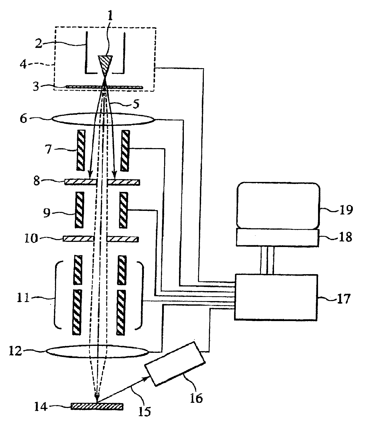
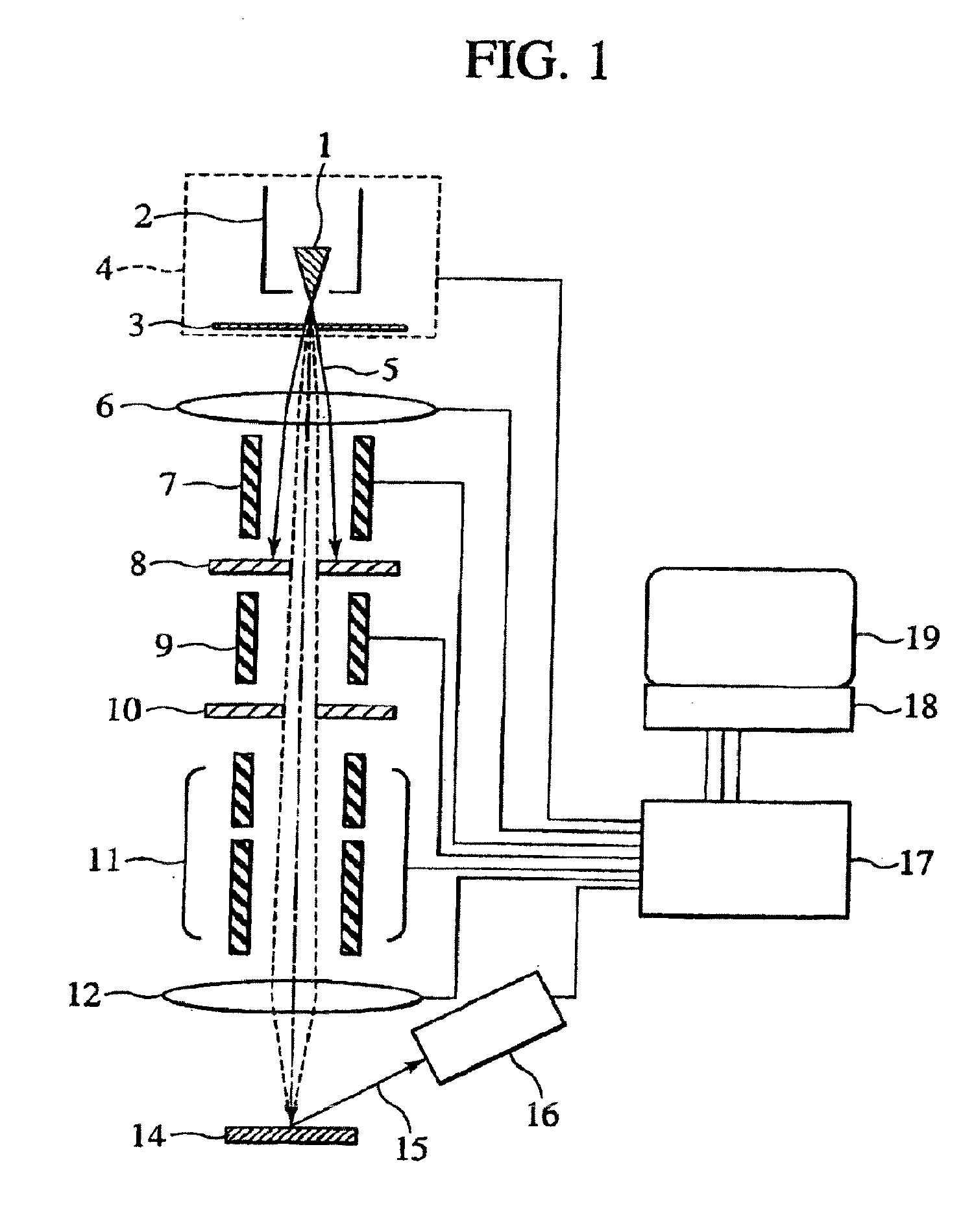
[0040]FIG. 1 schematically shows the construction of a scanning charged particle microscope equipped with a GFIS. The ions 5 emitted from the emitter 1 of the GFIS 4 are focused onto a specimen 14 by a focusing lens 6 and an objective lens 12. A beam deflector / aligner 7, a movable beam limiting aperture plate 8, a blanking electrode 9, a blank beam stop plate 10 and a beam deflector 11 are disposed between the two lenses. The secondary electrons 15 emitted from the specimen 14 are detected by a secondary electron detector 16. A beam controller 17 controls the GFIS 4, focusing lens 6, objective lens 12, upper beam deflector / aligner 7, lower beam deflector 11, secondary electron detector 16 and others. A personal computer 18 controls the beam controller 17 and processes / stores various data. An image display unit 19 displays SIM images and control screens of the PC 18.

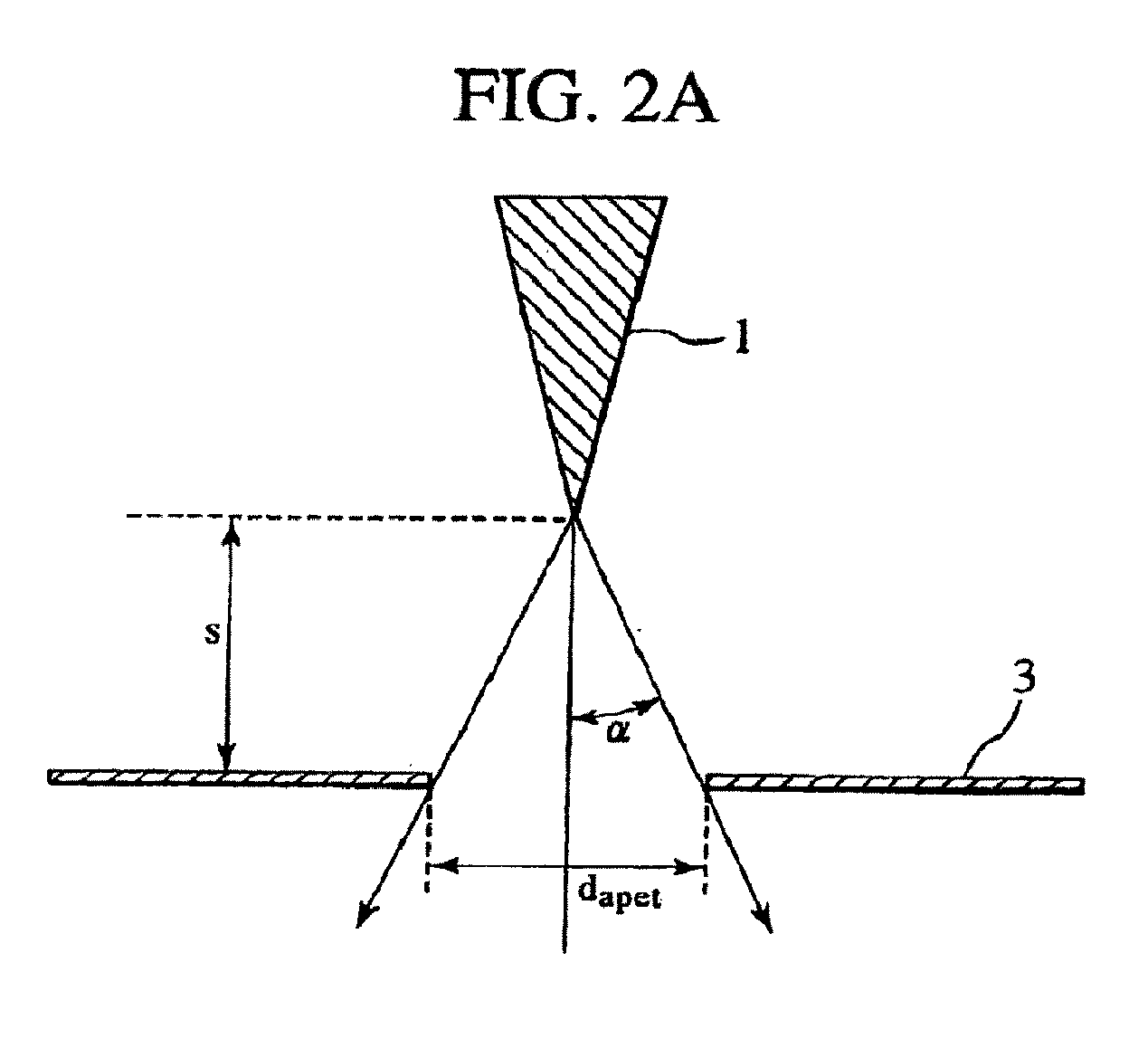
[0041]FIG. 2A is a diagram for explaining the relation between the emitter's tip and the hole diameter of the extractio...

embodiment 2

[0047]The present embodiment described below is a scanning charged particle microscope provided with changing means to change the aperture diameter dapture of the extraction electrode 3 which differs from the changing means employed in embodiment 1. The following description is focused on what are unique to the present embodiment.

[0048]The changing means of the present embodiment is structurally similar to the variable aperture employed in cameras and others. Plural diaphragm blades are combined so as to have a circular aperture which can coaxially be varied in diameter by changing the amount of overlap between diaphragm blades. By employing such means to change the aperture diameter of the extraction electrode, it is possible to not only let widely emitted ions go through but also, in behalf of differential pumping, reduce the diameter of the aperture.

embodiment 3

[0049]The present embodiment is a scanning charged particle microscope provided with changing means to change the aperture diameter daperture of the extraction electrode 3 which differs from the changing means employed in either embodiment 1 or 2. The following description is focused on what are unique to the present embodiment.

[0050]As shown in FIG. 4, the changing means of the present embodiment can be separated into an aperture-forming part 3d having an aperture through which ions extracted by the extraction electrode are passed, and a mounting part 3c on which the aperture-forming part 3d is mounted. The aperture-forming part 3d can be moved to and withdrawn from the optical axis 20. The aperture-forming part 3 is located as indicated with reference numeral 3d′ if the aperture-forming part 3 is withdrawn from the optical axis 20 by sliding it on the mounting part 3c.


PUM


Abstract

A gas field ionization ion source (GFIS) is characterized in that the aperture diameter of the extraction electrode can be set to any of at least two different values or the distance from the apex of the emitter to the extraction electrode can be set to any of at least two different values. In addition, solid nitrogen is used for cooling. It may be possible to not only let divergently emitted ions go through the aperture of the extraction electrode but also, in behalf of differential pumping, reduce the diameter of the aperture. In addition, it may be possible to reduce the physical vibration of the cooling means. Consequently, it may be possible to provide a highly stable GFIS and a scanning charged particle microscope equipped with such a GFIS.

Description

RELATED APPLICATIONS[0001]This application is the U.S. National Phase under 35 U.S.C. §371 of International Application No. PCT / JP2011 / 064478, filed on Jun. 23, 2011, which in turn claims the benefit of Japanese Application No. 2010-151119, filed on Jul. 1, 2010, and Japanese Application No. 2010-238711, filed on Oct. 25, 2010, the disclosures of which Applications are incorporated by reference herein.BACKGROUND OF THE INVENTION[0002]1. Field of the Invention[0003]The present invention relates to charged particle microscopes for observing surfaces of such specimens as semiconductor devices and new materials. For example, the invention relates to a scanning charged particle microscope which uses light ions as charged particles for shallow surface observation of a specimen with a high resolution and a large depth of focus, and a gas field ionization ion source for generating ions therein.[0004]2. Description of the Related Art[0005]Non-Patent Document 1 describes a focused ion beam (a...

Claims


Application Information

Patent Timeline
Patent Type & Authority Applications(United States)
IPC IPC(8): H01J37/285H01J27/26H01J37/04H01J37/08H01J37/28
CPCB82Y15/00H01J37/285H01J27/26H01J37/08H01J37/09H01J37/18H01J37/28H01J2237/002H01J2237/0216H01J2237/024H01J2237/032H01J2237/0458H01J2237/061H01J2237/0807H01J2237/0835H01J2237/1501H01J2237/188H01J2237/24514H01J27/024
Inventor ISHITANI, TOHRUOSE, YOICHISHICHI, HIROYASUMATSUBARA, SHINICHIHASHIZUME, TOMIHIROFUKUDA, MUNEYUKI
Owner HITACHI HIGH-TECH CORP
Why Eureka
Try Eureka