Light source module and projection apparatus

a technology which is applied in the direction of lighting and heating apparatus, instruments, optics, etc., can solve the problems of not being environmentally friendly, and not being suitable for light source, so as to reduce the interference between the exciting beam and the first color beam, and reduce the size of light source module and projection apparatus

Inactive Publication Date: 2013-04-11
YOUNG OPTICS
View PDF3 Cites 42 Cited by
  • Summary
  • Abstract
  • Description
  • Claims
  • Application Information

AI Technical Summary

Benefits of technology

[0015]According to the above descriptions, the embodiments of the invention have at least one of the following advantages or effects. In the embodiments of the invention, the light emitting wheel converts the first color beam through an exciting approach, so that the first color beam may ...

Problems solved by technology

However, the UHP lamp uses heavy metal mercury, so it is not an environment-friendly light source.
Nevertheless, the luminance of the conventional projectors using LEDs as light sources is relatively low, which is not suitable to serve as a light source of a high brightness projector.
However, a shift of a light spot occurs due to the dual light combination modu...

Method used


Image

  • Light source module and projection apparatus
  • Light source module and projection apparatus
  • Light source module and projection apparatus

Examples


first embodiment

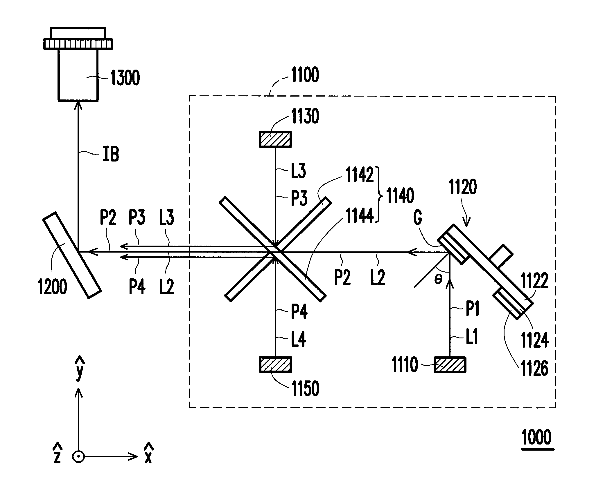
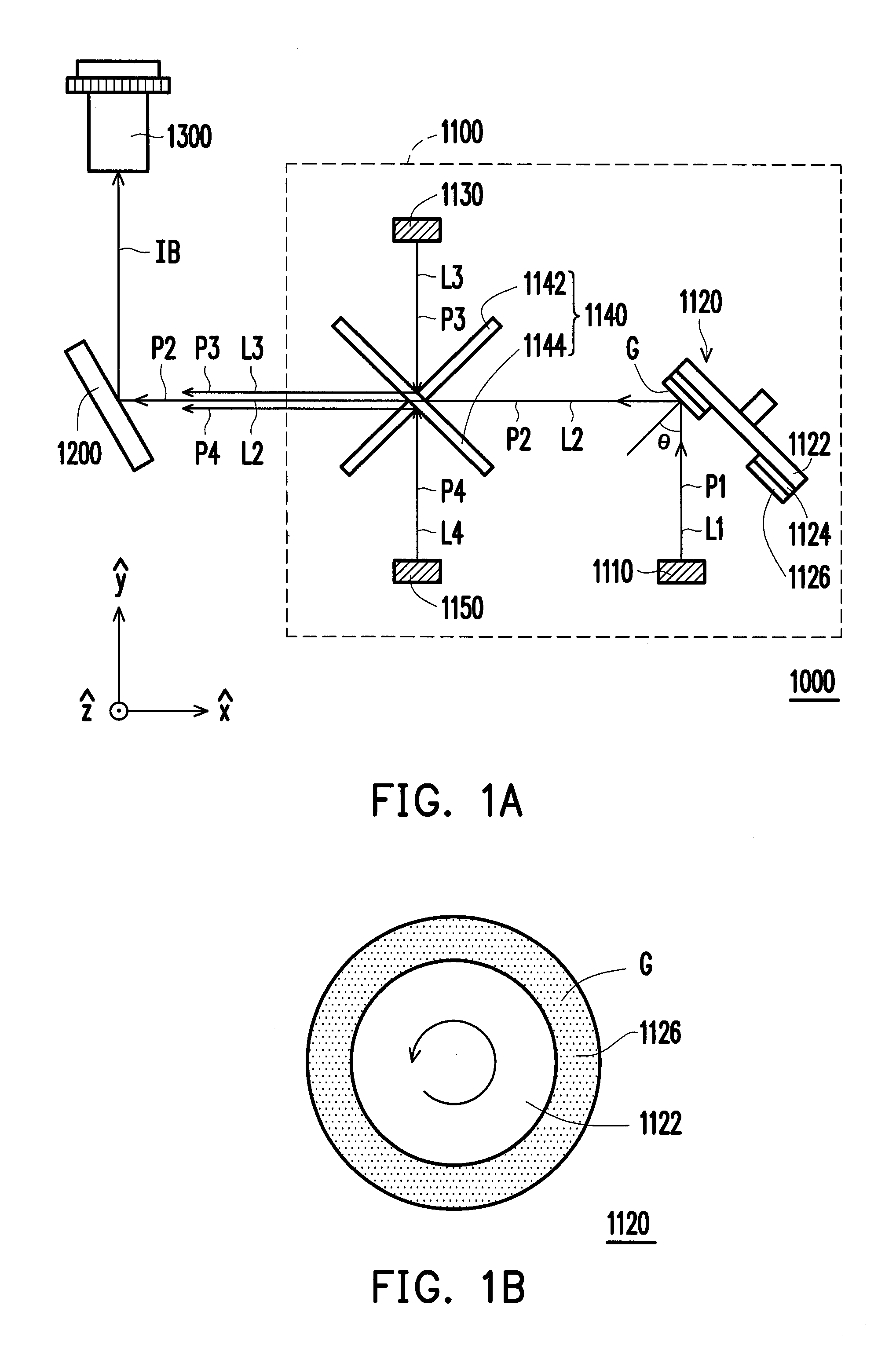
[0033]FIG. 1A is a schematic diagram illustrating a projection apparatus 1000 according to a first embodiment of the invention. FIG. 1B is a top view of a light emitting wheel 1120 of FIG. 1A. Referring to FIG. 1A, the projection apparatus 1000 of the embodiment includes a light source module 1100, a light valve 1200 and a projection lens 1300. The light source module 1100 includes a light-emitting device 1110, a light emitting wheel 1120, a light-emitting device 1130, and a light combination device 1140.

[0034]The light-emitting device 1110 provides an exciting beam L1. In the embodiment, the first light-emitting device 1110 is, for example, a blue solid-state laser or an ultraviolet (UV) laser, and a wavelength range of the exciting beam L1 is, for example, between 380 nm and 460 nm.

[0035]Referring to FIGS. 1A and 1B, the light emitting wheel 1120 is disposed on a transmission path P1 of the exciting beam L1 and has a light conversion area G. As shown in FIG. 1A, the exciting beam ...

second embodiment

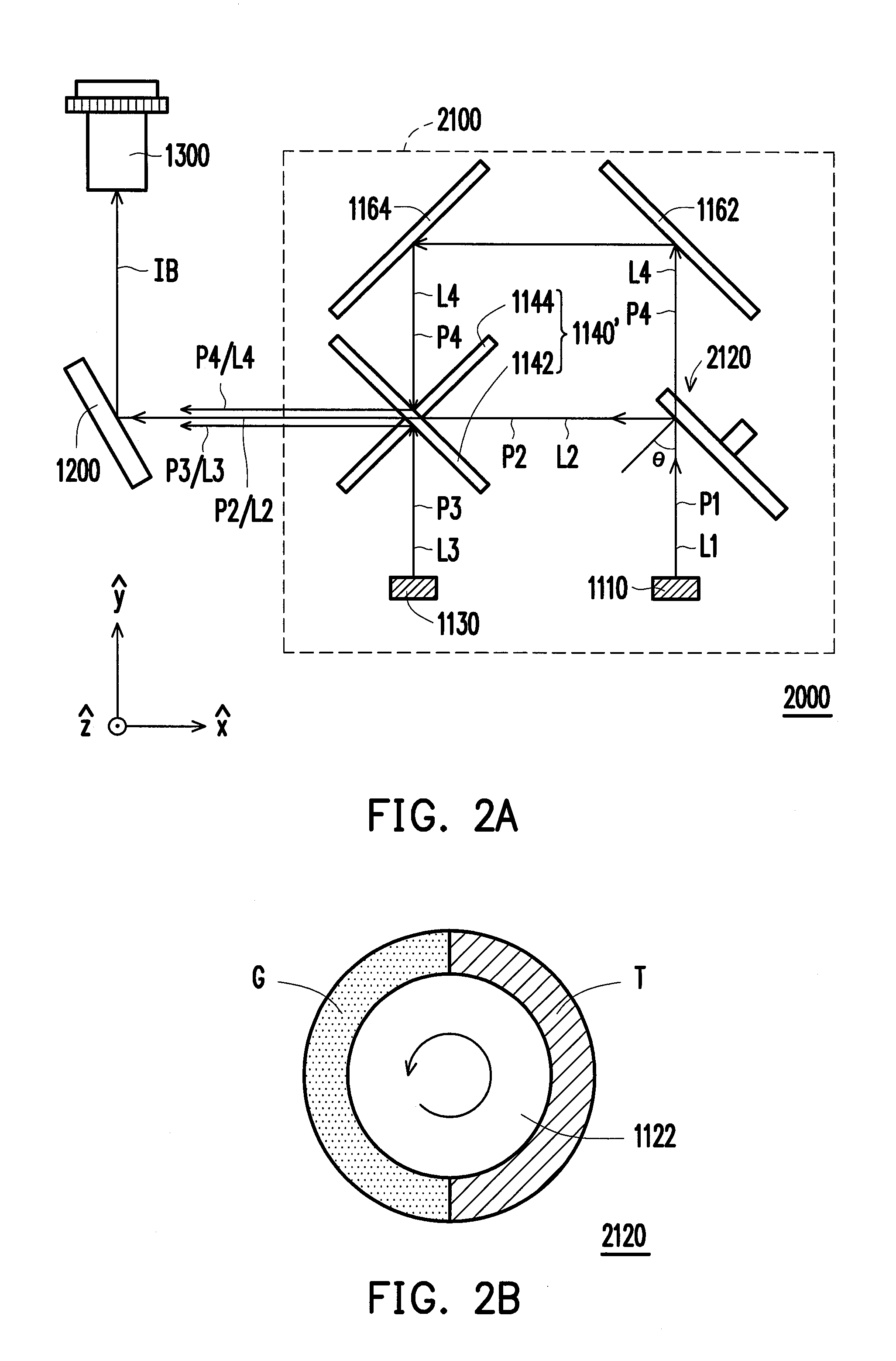
[0040]FIG. 2A is a schematic diagram of a projection apparatus 2000 according to a second embodiment of the invention. FIG. 2B is a top view of a light emitting wheel 2120 of FIG. 2A. FIG. 2C is the cross-section of the light emitting wheel 2120 of FIG. 2A. The projection apparatus 2000 of the embodiment is similar to the projection apparatus 1000 of FIG. 1A, while a main difference therebetween lies in the light emitting wheel 2120 further has a light-transmissive area T as shown in FIG. 2B and FIG. 2C. The light-transmissive area T transmits the exciting beam L1, and the exciting beam L1 passing through the light-transmissive area T is used as the color beam L4 of FIG. 1A. Specifically, the color beam L4 of FIG. 1A is provided by the light emitting diode 1150, while the color beam L4 of FIG. 2A is from the exciting beam L1. In the embodiment, the exciting beam L1 is, for example, a blue laser, and the color beam L4 is a blue beam.

[0041]As shown in FIG. 2C, the light emitting wheel...

third embodiment

[0045]FIG. 3A is a schematic diagram of a projection apparatus 3000 according to a third embodiment of the invention. FIG. 3B is a top view of a light emitting wheel 3120 of FIG. 3A. The projection apparatus 3000 of the embodiment is similar to the projection apparatus 1000 of FIG. 1A, while a main difference therebetween lies in the light emitting wheel 3120 further has a light conversion area R as shown in FIG. 3B. Referring to FIG. 3A, a light source module 3100 of the projection apparatus 3000 includes the light-emitting device 1110, a light emitting wheel 3120 and a light-emitting device 3130. Herein, the light emitting wheel 3120 has the light conversion area G and the light conversion area R as shown in FIG. 3B. The fluorescence layers 1126 of the light conversion areas G and R are respectively a green fluorescence layer and a red fluorescence layer, for example. The exciting beam L1 obliquely irradiates on the light conversion area G and is converted into the color beam L2 w...


PUM


Abstract

A light source module including a first light-emitting device, a light emitting wheel, a second light-emitting device, and a light combination device is provided. The first light-emitting device provides an exciting beam. The light emitting wheel is disposed on a transmission path of the exciting beam and has a first light conversion area. The exciting beam obliquely irradiates on the first light conversion area and is converted into a first color beam. The second light-emitting device provides a second color beam. Herein, colors of the first color beam and the second color beam are different. The light combination device is disposed on the transmission paths of the first color beam and the second color beam. The first color beam is reflected to the light combination device by the light emitting wheel and the light combination device combines the first color beam and the second color beam.

Description

BACKGROUND OF THE INVENTION[0001]1. Field of the Invention[0002]The invention relates to a light source module and a projection apparatus. More particularly, the invention relates to a light source module and a projection apparatus having high brightness.[0003]2. Description of Related Art[0004]Currently, multimedia projectors usually use an ultra high pressure mercury lamp (UHP lamp) as a light source. The UHP lamp has advantages of high efficient and high luminance, which has good performance in the light flux of the projectors. However, the UHP lamp uses heavy metal mercury, so it is not an environment-friendly light source. Thus, with the increasing environmental awareness as well as the development of display technology, in recent years, a projector using red, green and blue light-emitting diodes (LEDs) as light sources is further developed.[0005]Compared with the UHP lamps, the LED is much thinner and smaller, and the energy consumption of the LED is much lower. Besides, the L...

Claims


Application Information

Patent Timeline
IPC IPC(8): G03B21/14F21V9/00
CPCG03B21/204H04N9/3161H04N9/3114G03B33/08
Inventor LIN, HSIN-HUNGCHANG, YU-YUNCHOU, HUNG-CHIHPAN, HAW-WOEICHEN, CHAO-SHUN
Owner YOUNG OPTICS
Why Eureka
Try Eureka