
Radiological imaging device

a radiographic image and imaging device technology, applied in the field of radiographic image capturing apparatus, can solve the problems of increasing fabrication costs, affecting the accuracy of radiographic images, so as to improve the uniformity of radiographic images in the plane, and improve the accuracy of correction. the effect of accuracy

Inactive Publication Date: 2013-04-18
FUJIFILM CORP
View PDF3 Cites 15 Cited by
  • Summary
  • Abstract
  • Description
  • Claims
  • Application Information

AI Technical Summary

Benefits of technology

The patent is about a device that increases the number of parts and requires a separate fabrication process, resulting in higher costs.

Problems solved by technology

Further, a separate fabrication process is needed, resulting in an increase in fabrication costs.
If heat is stored in an assembly of bonded materials having different coefficients of thermal expansion, then the materials tend to peel off and crack due to thermal stresses produced at interfaces between the bonded materials, thereby impairing intimate contact between such materials.
Therefore, the circuit boards of such electronic cassettes are likely to give off a large amount of heat.
As disclosed in Japanese Laid-Open Patent Publication No. 2007-101256, if a resin material having a high coefficient of thermal expansion is used as a circuit board material, then a problem of impaired intimate contact between the circuit board and the base table on which the radiation conversion panel is mounted arises, similar to the case of the aforementioned scintillator and solid-state detector.

Method used


Image

  • Radiological imaging device
  • Radiological imaging device
  • Radiological imaging device

Examples


first embodiment

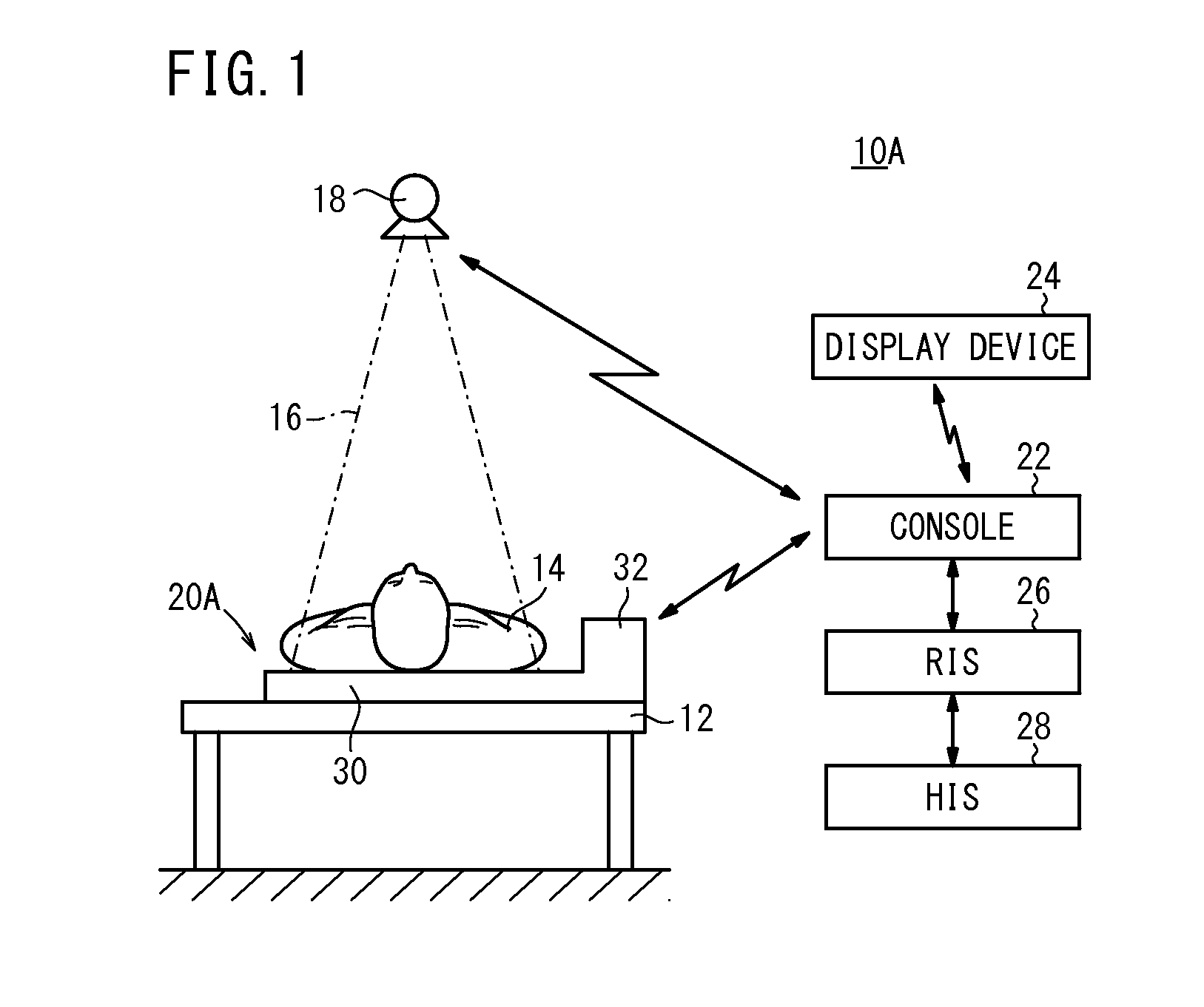
[0047]A radiographic image capturing system 10A according to the present invention will be described below with reference to FIGS. 1 through 7.

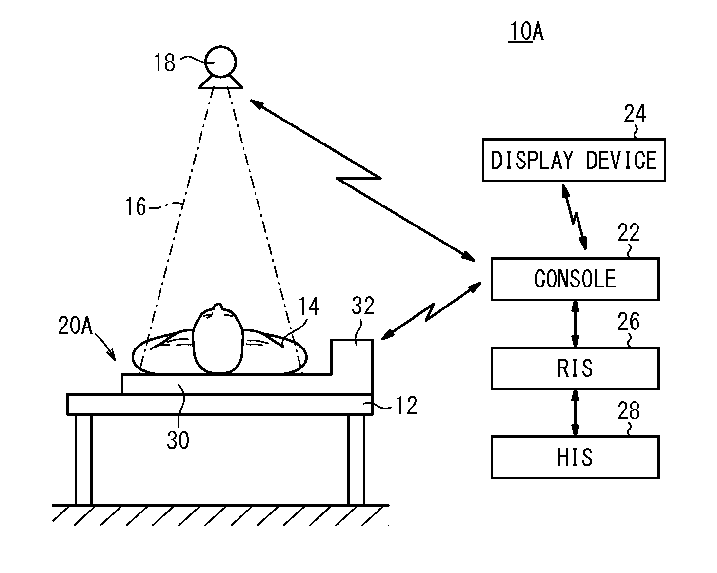
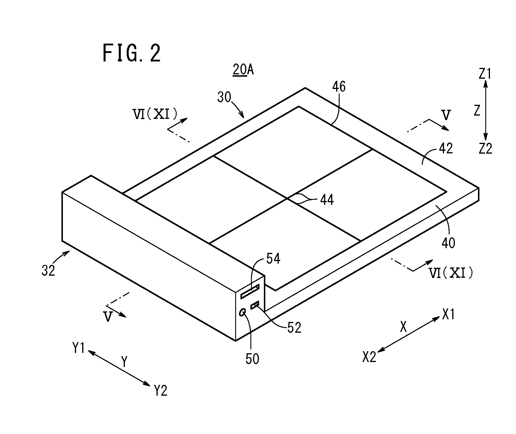
[0048]As shown in FIG. 1, the radiographic image capturing system 10A has a radiation source 18 for applying radiation 16 of a dose according to image capturing conditions to a subject 14 as a patient lying on an image capturing base 12 such as a bed or the like, an electronic cassette (radiographic image capturing apparatus) 20A for detecting radiation 16 that has passed through the subject 14 and converting the detected radiation 16 into a radiographic image, a console 22 for controlling the radiation source 18 and the electronic cassette 20A, and a display device 24 for displaying radiographic images.

[0049]The console 22, the radiation source 18, the electronic cassette 20A, and the display device 24 send signals to and receive signals from each other via a wireless communication link such as an UWB (Ultra Wide Band) communication link, a ...

second embodiment

[0114]An electronic cassette 20B and a radiographic image capturing system 10B according to the present invention will be described below with reference to FIGS. 12 through 15.

[0115]Parts of the electronic cassette 20B and the radiographic image capturing system 10B, which are identical to those of the electronic cassette 20A and the radiographic image capturing system 10A according to the first embodiment (see FIGS. 1 through 11), are denoted by identical reference characters, and such features will not be described in detail below.

[0116]As shown in FIGS. 12 and 13, the electronic cassette 20B and the radiographic image capturing system 10B according to the second embodiment differ from the electronic cassette 20A and the radiographic image capturing system 10A according to the first embodiment in that the panel housing unit 30 is free of a projecting part that functions as a control unit 32.

[0117]As shown in FIG. 13, the casing 40 has the AC adapter input terminal 50, the USB term...


PUM


Abstract

Disclosed is a radiological imaging device which comprises: a radiation conversion panel which is obtained by laminating a scintillator and a photoelectric conversion layer and converts a radiation ray into a radiation image; a base which supports the radiation conversion panel mounted thereon; and a case which houses the radiation conversion panel and the base. The base supports the radiation conversion panel, while deforming the radiation conversion panel into a convex shape with respect to the mounting direction thereof.

Description

CROSS-REFERENCE TO RELATED APPLICATIONS AND PRIORITY CLAIM[0001]This application is a Continuation of International Application No. PCT / JP2011 / 061878 filed on May 24, 2011, which was published under PCT Article 21(2) in Japanese, which is based upon and claims the benefit of priority from Japanese Patent Application No. 2010-119555 filed on May 25, 2010, the contents all of which are incorporated herein by reference.TECHNICAL FIELD[0002]The present invention relates to a radiographic image capturing apparatus (radiological imaging device) having a radiation conversion panel for converting radiation into a radiographic image, the radiation conversion panel comprising a stacked assembly made up of a scintillator and a photoelectric transducer layer, a base table supporting the radiation conversion panel which is placed thereon, and a casing housing therein the radiation conversion panel and the base table.BACKGROUND ART[0003]In the medical field, there have widely been used radiograph...

Claims


Application Information

Patent Timeline
IPC IPC(8): G01T1/20
CPCA61B6/4225A61B6/4283G01T1/2006G03B42/025G03B42/04G03B42/02
Inventor OHTA, YASUNORINISHINO, NAOYUKINAKATSUGAWA, HARUYASUIWAKIRI, NAOTO
Owner FUJIFILM CORP
Learn More