Doherty Power Amplifier Network

Active Publication Date: 2013-04-18
TTM TECH INC
View PDF2 Cites 43 Cited by
  • Summary
  • Abstract
  • Description
  • Claims
  • Application Information

AI Technical Summary

Benefits of technology

[0013]One aspect of the present invention is directed to a network that includes an output matching network coupled to an amplifier transistor that is characterized by at least one amplifier transistor output impedance. The output matching network includes an in-phase signal path disposed in parallel with a quadrature signal path. The output matching network is configured to transform the at least one amplifier transistor output impedance to an output matching network impedance. The output matching network impedance is intermediate the at least one amplifier transistor output impedance and a load impedance. A combiner network is coupled to the output matching network. The combiner network includes a first quarter wavelength transmission line coupled between the in-phase signal path and a combiner node. The first quarter wavelength transmission line is configured to substantially eliminate a phase delay between an in-phase signal and a quadrature signal. The combiner network further includes a bandwidth

Problems solved by technology

One of the biggest challenges facing cellular base station power amplifier manufacturers is the task of increasing the efficiency of linear power amplifiers for high peak-to-average ratio (PAR) signals in a linear power amplifier.
It shows that the bandwidth limitation is at low power mode.
The bandwidth limitation is due to the combination of transistor technology, matching networks and Doherty combining circuits.
The drawback of this approach, i

Method used


Image

  • Doherty Power Amplifier Network
  • Doherty Power Amplifier Network
  • Doherty Power Amplifier Network

Examples


first embodiment

[0026]As embodied herein, and depicted in FIGS. 3A-3B, schematic diagrams of a Doherty network in accordance with the present invention disclosed. The network 10 includes an output matching network 20 coupled to a Doherty combiner 30. The output matching network includes a quarter wave delay transmission line 22 coupled to a Doherty carrier amplifier (not shown); both of these elements are disposed in a quadrature signal path. The output matching network also includes a quarter wave delay transmission line 24 coupled to a Doherty peak amplifier (also not shown). Both of these elements are disposed in an in-phase signal path. The phase delay for each of the transmission lines (22, 24) in the matching network 20 has to be one quarter wave length to achieve the required Doherty operation. In the example embodiment of FIGS. 3A and 3B, the matching network 20 matches the carrier and peaking amplifiers to 25 ohms (instead of to the 50 ohm load).

[0027]The Doherty combiner includes a quarte...

second embodiment

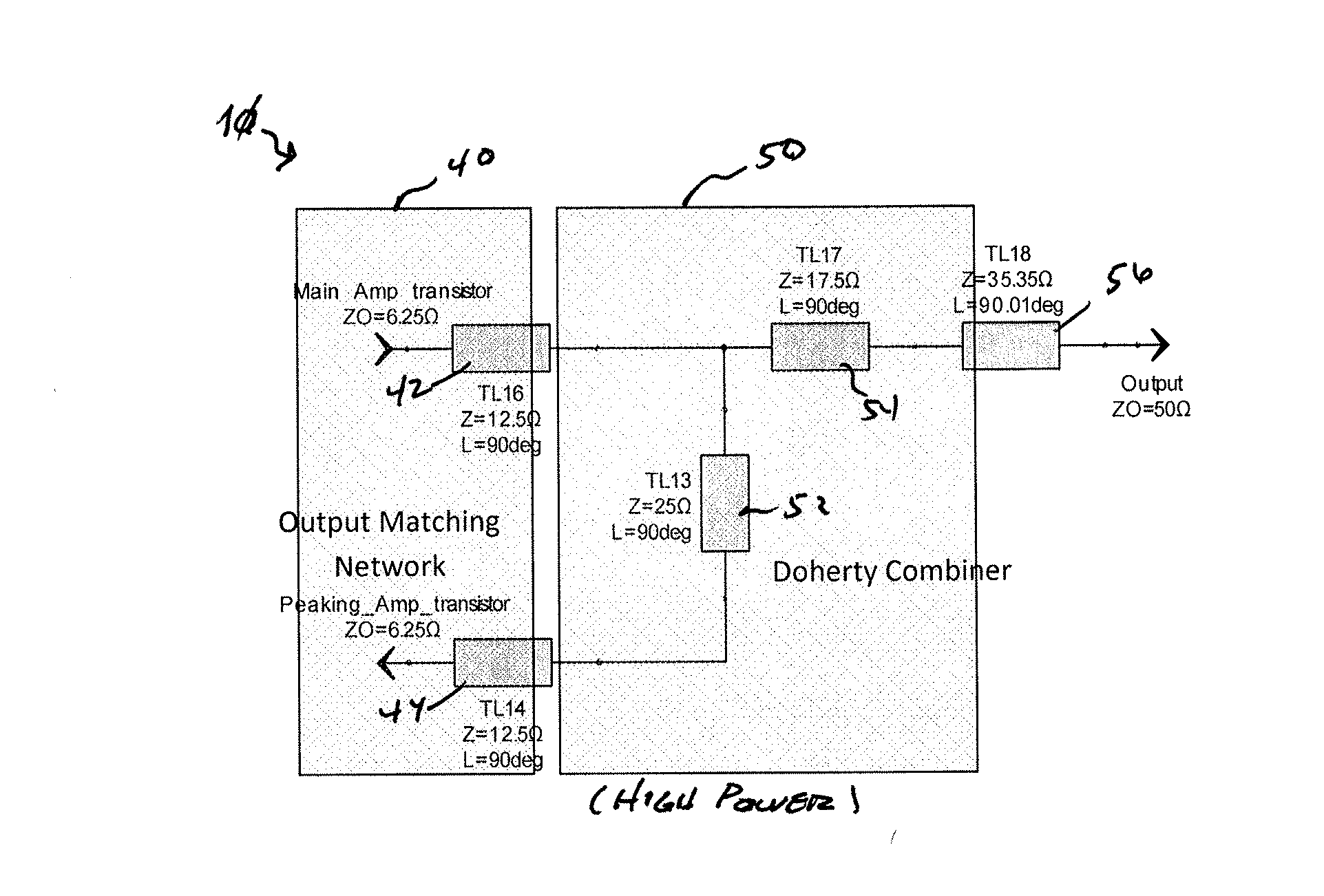
[0031]As embodied herein, and depicted in FIGS. 7A-7B, schematic diagrams of a Doherty architecture in accordance with the present invention is disclosed. In this embodiment, the output matching network 20 is identical to the one depicted in FIG. 3A. Moreover, the combiner network is similar to the one depicted in FIG. 3A. The difference between the combiner network shown in FIG. 3A-3B and the one depicted in this embodiment is that the 12.5 to 50 ohm impedance transformer (i.e., implemented by transmission lines 34 and 36 in FIGS. 3A-3B) is replaced by a two stage quarter wave length transformer (i.e., implemented by transmission lines 54 and 56 in FIGS. 7A-7B).

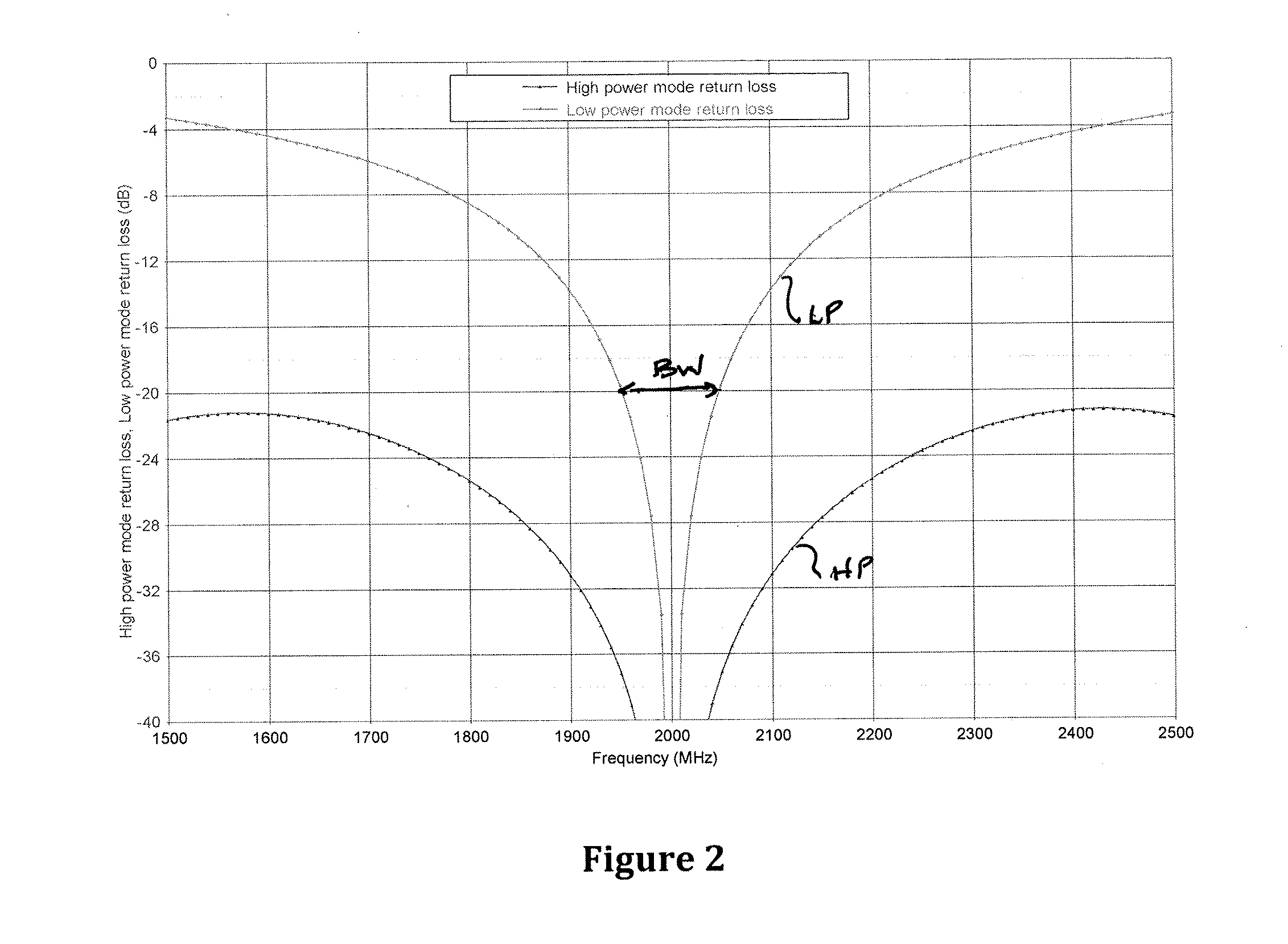
[0032]In reference to FIG. 8, a chart illustrating the performance of the Doherty architecture depicted in FIGS. 7A-7B is disclosed. This embodiment provides a 600 MHz bandwidth at 2.0 GHz (from 1700 MHz to 2300 MHz in the plot). While the performance of this embodiment is less than that achieved by the first embodiment, it ...


PUM


Abstract

The present invention is directed to a network that includes an output matching network coupled to an amplifier. The output matching network is configured to transform the at least one amplifier transistor output impedance to an output matching network impedance. A combiner network is coupled to the output matching network. The combiner network includes a first quarter wavelength transmission line coupled between the in-phase signal path and a combiner node. The combiner network further includes a bandwidth enhancement element coupled to the quadrature signal path at the combiner node and an impedance transformation element coupled between the combiner node and a load. The impedance transformation element is configured to substantially transform a combined output matching network impedance at the combiner node to the load impedance.

Description

CROSS-REFERENCE TO RELATED APPLICATIONS[0001]This is application is related to U.S. Provisional Patent Application Ser. No. 61 / 547,277 filed on Oct. 14 2011, and U.S. Provisional Patent Application Ser. No. 61 / 569,827 filed on Dec. 13, 2011, the contents of which is relied upon and incorporated herein by reference in their entirety, and the benefit of priority under 35 U.S.C. §119(e) is hereby claimed.BACKGROUND OF THE INVENTION[0002]1. Field of the Invention[0003]The present invention relates generally to power amplifiers, and particularly to Doherty power amplifiers.[0004]2. Technical Background[0005]One of the biggest challenges facing cellular base station power amplifier manufacturers is the task of increasing the efficiency of linear power amplifiers for high peak-to-average ratio (PAR) signals in a linear power amplifier. At same time, the competition on a global scale has created a requirement for base stations to support a wider range of frequency bands, as new spectrum is ...

Claims


Application Information

Patent Timeline
IPC IPC(8): H01P5/12H03F3/68
CPCH01P5/12H03F1/0288H03F2200/387H03F3/602H03F1/56
Inventor MEI, CHONG
Owner TTM TECH INC
Why Eureka
Try Eureka