Down converter

a voltage converter and converter technology, applied in the field of voltage converters, can solve the problems of damage to the switch sb>3/b>, etc., and achieve the effect of not reducing the efficiency of the voltage converter and reducing the voltage load on the switch s3

Inactive Publication Date: 2013-04-18
MINEBEAMITSUMI INC
View PDF5 Cites 8 Cited by
  • Summary
  • Abstract
  • Description
  • Claims
  • Application Information

AI Technical Summary

Benefits of technology

[0012]This object has been achieved according to the invention in that the output switch is connected via a diode to another circuit part, particularly to the DC voltage input or the DC voltage output. This allows the excess voltage of the voltage overshoots to be diverted to another component of the circuit. The voltage load on the switch S3 is thereby reduced to the simple input voltage. Oscillation of the parasitic resonance circuit is likewise prevented, so that no additional EMC emissions occur and the efficiency of the voltage converter is not reduced.

Problems solved by technology

These voltage overshoots pose a threat to the switch S3 which could be damaged by the high voltage.
Moreover, the voltage oscillations cause undesired EMC emissions and reduce the efficiency of the voltage converter.

Method used


Image

  • Down converter
  • Down converter
  • Down converter

Examples


Embodiment Construction

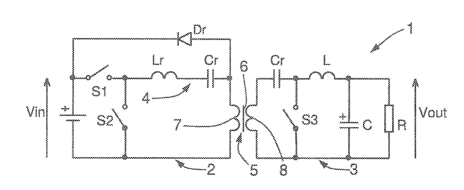
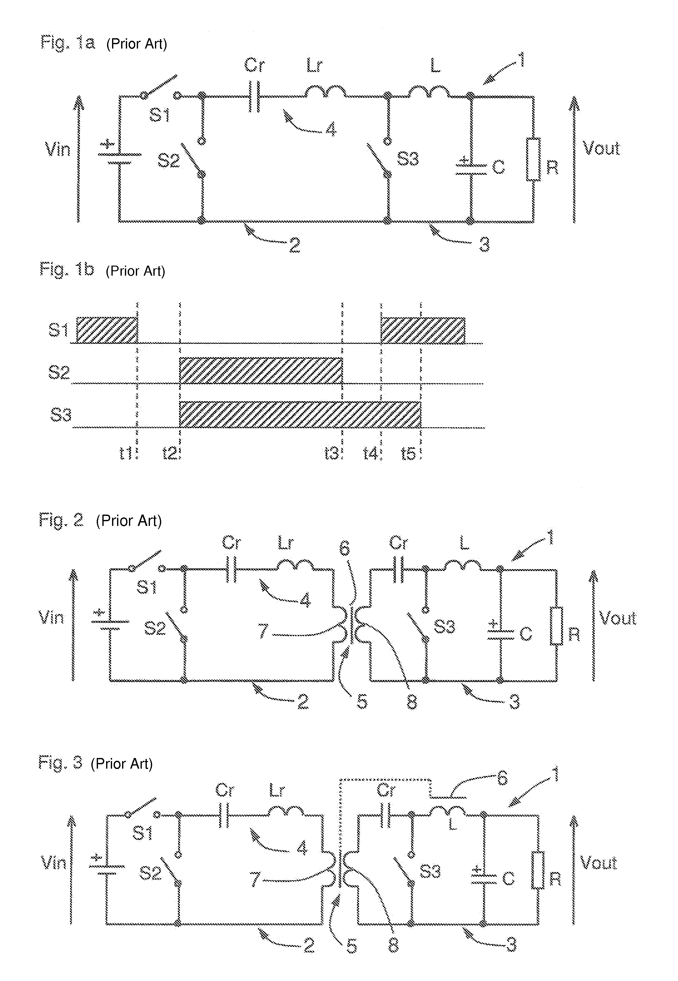
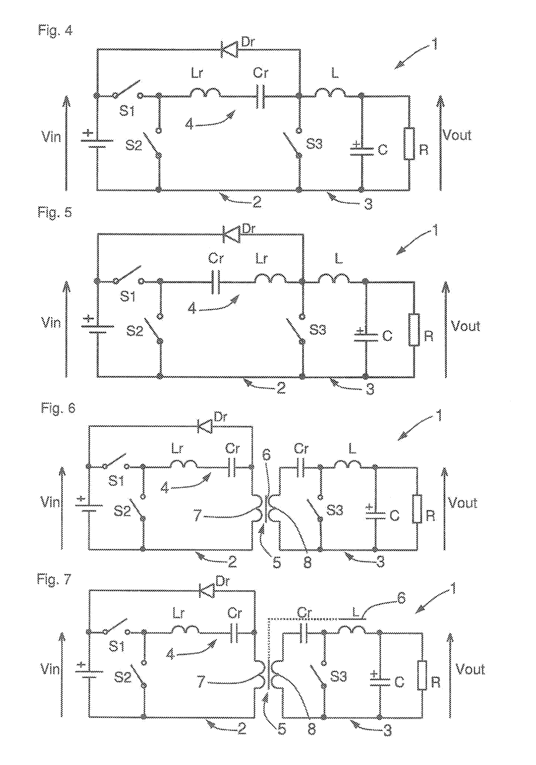
[0036]FIG. 4 shows a first embodiment of a voltage converter 1 according to the invention that substantially corresponds to the circuit of FIG. 1a.

[0037]In this embodiment, the excess energy is diverted into the capacitor Cr of the LC resonance circuit 4. For this purpose, the anode of a diode Dr is connected to the output switch S3 and the cathode of the diode Dr is connected to the input DC voltage before the switch S1.

[0038]Since the voltage overshoots at S3 only occur when S1 is switched on, through this arrangement the diode is also only connected at that time to the LC resonance circuit, so that in the free-running phase no impairment occurs due to the diode Dr.

[0039]In the illustrated embodiment, the capacitor Cr is positioned first in the LC resonance circuit and the inductor Lr afterwards. The circuit functions without restriction even if the positions of the capacitor Cr and the coil Lr are interchanged as illustrated in FIG. 5.

[0040]The diversion of voltage peaks accordi...


PUM


Abstract

A down converter for converting an input DC voltage (Vin) into a lower output DC voltage (Vout). The down converter has on the primary side (2) an LC series resonance circuit (4) that can be connected via a first switch (S1) to the input voltage (Vin) and via a second switch (S2) to ground. On the secondary side (3), an output switch (S3) and an output capacitor (C) are each connected in parallel to the DC voltage output (Vout) and connected to each other through an inductor (L). The output switch (S3) is connected via a diode (Dr) to the input voltage (Vin) so as to divert voltage overshoots.

Description

INCORPORATION BY REFERENCE[0001]The following documents are incorporated herein by reference as if fully set forth: German Patent Application No. DE 10 2011 120 805.8, filed Dec. 10, 2012.BACKGROUND[0002]The invention is directed to a voltage converter, particularly a down converter, for converting an input DC voltage into a lower output DC voltage.[0003]Such a down converter, also called a step-down converter or buck converter, according to the prior art is shown in FIG. 1 by way of example. The down converter has a primary side 2 having a DC voltage input Vin and a secondary side 3 having a DC voltage output Vout. Disposed on the primary side 2 is an LC series resonance circuit 4 made up of a coil Lr and a capacitor Cr that can be connected via a first switch S1 to the input voltage Vin and via a second switch S2 to ground. On the secondary side 3, an output switch S3 and an output capacitor C are each connected in parallel to the DC voltage output Vout and connected to each other...

Claims


Application Information

Patent Timeline
Patent Type & Authority Applications(United States)
IPC IPC(8): H02M3/335
CPCH02M3/33523H02M3/33569H02M3/158H02M3/33571H02M3/01H02M1/42
Inventor WEGER, ROBERTRAYKHMAN, MYKHAYLO
Owner MINEBEAMITSUMI INC
Why Eureka
Try Eureka