Eureka AIR delivers breakthrough ideas for toughest innovation challenges, trusted by R&D personnel around the world.

Fuel cell system and control method therefor

a fuel cell and control method technology, applied in the field of fuel cells, can solve the problems of single cell part generating negative voltage, single cell part supplying reaction gases, fuel cell overall deteriorating power generation performance, etc., and achieve the effect of suppressing performance deterioration

Active Publication Date: 2013-04-18
TOYOTA JIDOSHA KK
View PDF1 Cites 30 Cited by
  • Summary
  • Abstract
  • Description
  • Claims
  • Application Information

AI Technical Summary

Benefits of technology

The patent is about a way to prevent a fuel cell from becoming less efficient and breaking down because of negative voltage.

Problems solved by technology

However, if the gas flow passages of part of the single cells are blocked by frozen water content, or the like, the amounts of reaction gases supplied to the part of the single cells become insufficient, so the part of the single cells may possibly generate negative voltage.
In this way, when the operation of the fuel cell is continued in a state where part of the single cells generate negative voltage, not only the power generation performance of the fuel cell overall deteriorates but also the electrodes of those single cells may possibly degrade.

Method used


Image

  • Fuel cell system and control method therefor
  • Fuel cell system and control method therefor
  • Fuel cell system and control method therefor

Examples


first alternative embodiment

[0157]In the above described embodiments, the control unit 20 stores the oxygen consumption rate map MGV as the correlation between an accumulated current value and an oxygen consumption rate in the storage unit, and stores the current density threshold map MTC as the correlation between a current density and an oxygen production rate in the storage unit. However, these correlations do not need to be stored as maps; instead, for example, these correlations may be stored as arithmetic expressions or functions. Note that the same applies to the various maps described in the above described embodiments.

second alternative embodiment

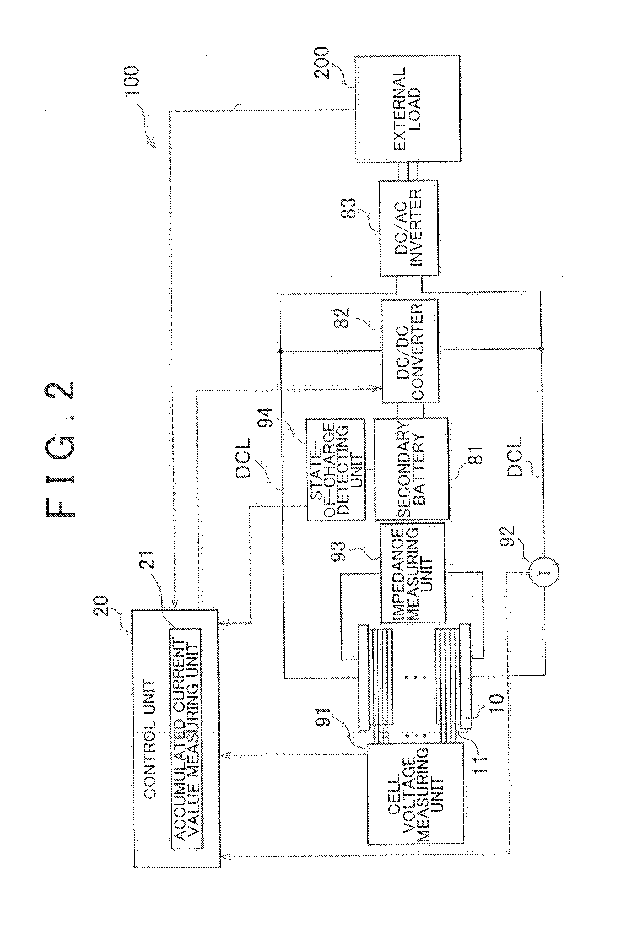
[0158]In the above described embodiments, the cell voltage measuring unit 91 measures the voltages of ah the power generating elements 11 of the fuel cell 10 to thereby detect negative voltage. However, the cell voltage measuring unit 91 does not need to measure the voltages of all the power generating elements 11; the cell voltage measuring unit 91 just needs to measure the voltage of at least one of the power generating elements 11 to thereby detect negative voltage. For example, it is known that it is highly likely that negative voltage occurs In the power generating element 11 arranged at the end portion of the fuel cell 10, at which the operating temperature tends to be the lowest, among the power generating elements 11. Then, the cell voltage measuring unit 91 may measure, the voltage of only the power generating element 11 arranged at the end portion to detect negative voltage.

third alternative embodiment

[0159]In the first embodiment, the control unit 20 uses the oxygen consumption rate map MGV and the current density threshold map MTC to determine the current density threshold imax so as to reduce oxygen present in the anode of the negative voltage cell 11. Instead, the control unit 20 may use a single map that indicates the correlation between an accumulated current value and a current density, which is a combination of the oxygen consumption rate map MGV and the current density threshold map MTC, to acquire a current density threshold against an accumulated current value in a period during winch negative voltage is generated.

[0160]In addition, the control unit 20 may prestore, in the storage unit, the correlation between an accumulated current value in a period during which negative voltage is generated and a current density at or below which the negative voltage cell 11 may recover from negative voltage by increasing the amount of supplied hydrogen, instead of the oxygen consump...


PUM


Abstract

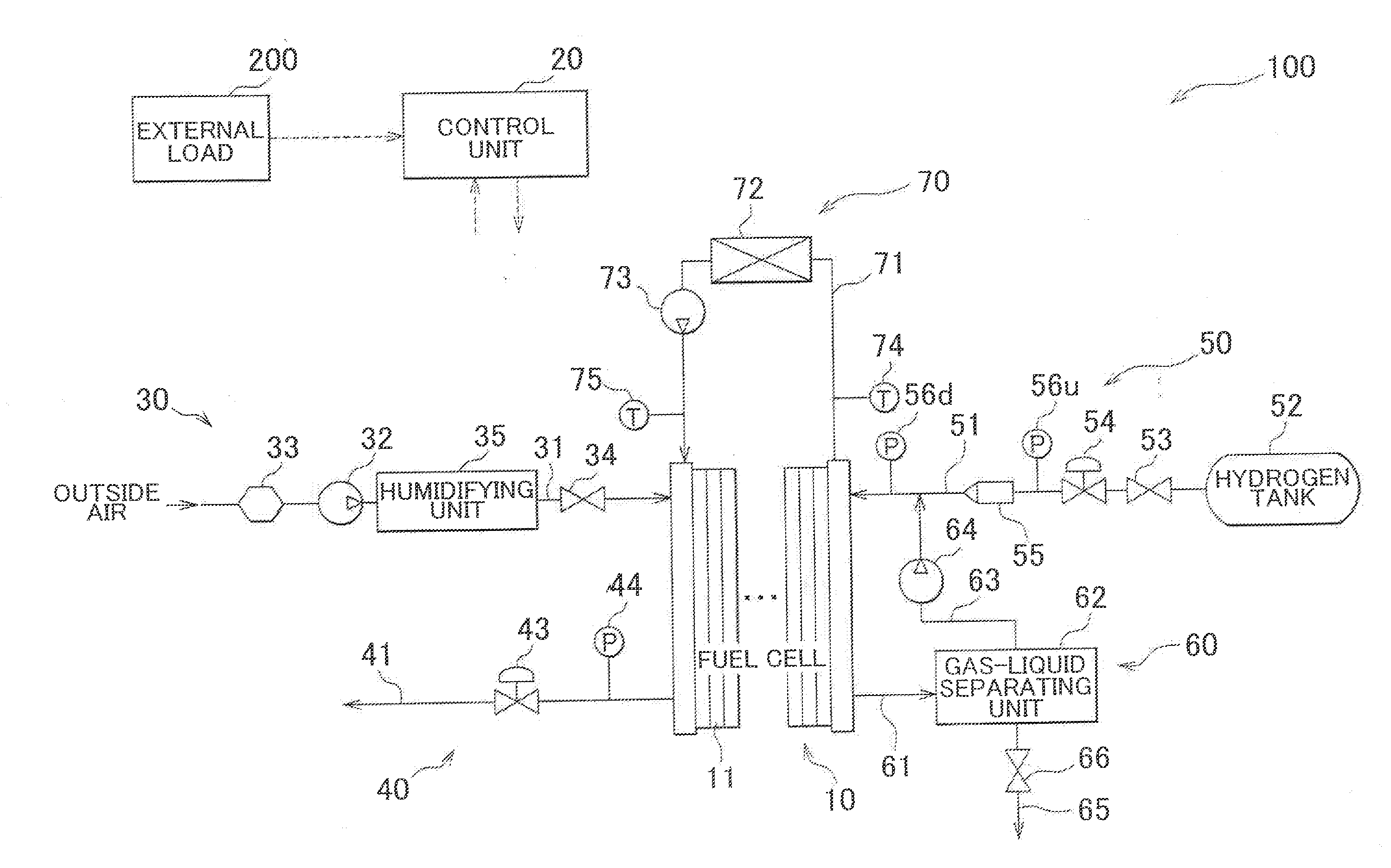
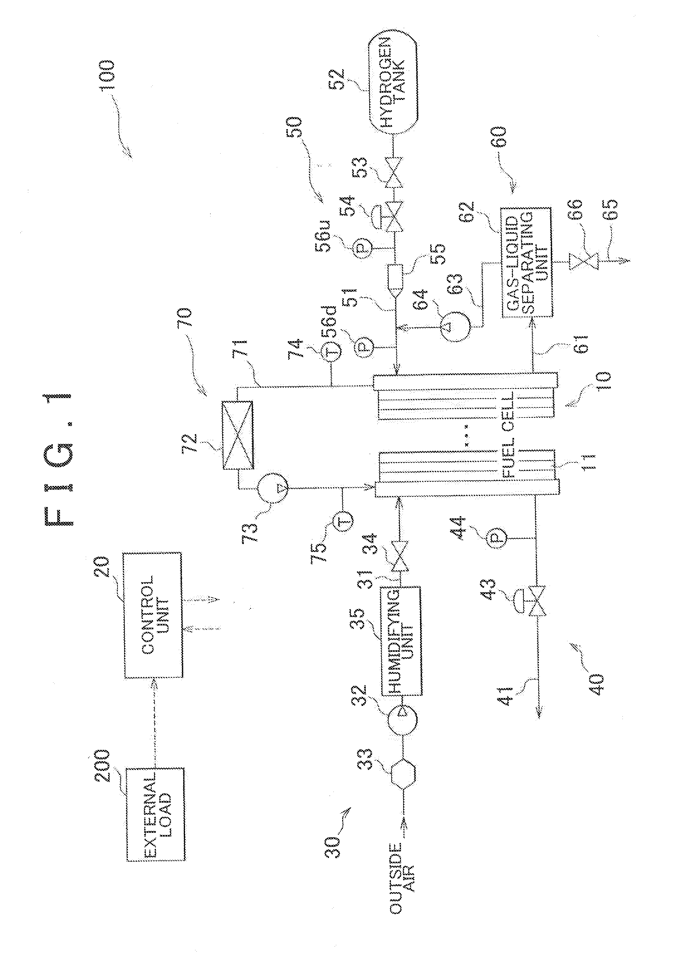
A fuel cell system includes an accumulated current value measuring unit. The accumulated current value measuring unit measures an accumulated current value by time integration of current output from the fuel cell in a period during which oxygen is produced by water-splitting reaction in an anode of a negative voltage cell. A control unit uses a first correlation between the accumulated current value in the oxygen generation period and an oxygen consumption rate in the anode and a second correlation between a current density of the fuel cell in the oxygen generation period and an oxygen production rate in the anode to obtain a current density at or below which the amount of oxygen in the anode may be reduced, and causes the fuel cell to output electric power at a current density lower than the obtained current density.

Description

BACKGROUND OF THE INVENTION[0001]1. Field of the Invention[0002]The invention relates to a fuel cell.[0003]2. Description of Related Art[0004]A fuel cell usually has a stack structure in which a plurality of single cells that serve as power generating elements are stacked. Reaction gases flow into gas flow passages, provided for each single cell, via respective manifolds and are supplied to a power generating portion of each single cell. However, if the gas flow passages of part of the single cells are blocked by frozen water content, or the like, the amounts of reaction gases supplied to the part of the single cells become insufficient, so the part of the single cells may possibly generate negative voltage. In this way, when the operation of the fuel cell is continued in a state where part of the single cells generate negative voltage, not only the power generation performance of the fuel cell overall deteriorates but also the electrodes of those single cells may possibly degrade. ...

Claims


Application Information

Patent Timeline
IPC IPC(8): H01M8/04H01H35/00
CPCH01M8/04552H01M8/04574Y02E60/50H01M8/0491H01M8/0494H01M8/04671
Inventor KAWAHARA, SHUYAKATO, MANABU
Owner TOYOTA JIDOSHA KK
Why Eureka
Eureka Blog
Learn More