Methods and systems for automatic rolling-element bearing fault detection

Inactive Publication Date: 2013-04-18
GENERAL ELECTRIC CO
View PDF8 Cites 54 Cited by
  • Summary
  • Abstract
  • Description
  • Claims
  • Application Information

AI Technical Summary

Problems solved by technology

Therefore, at least some known bearing monitoring systems are generally only capable of detecting bearing faults that produce expected frequencies.
Thus, a bearing monitoring system may ignore some frequencies that may be indicative of bearing faults simply because the bearing monitoring system is not configured to examine such frequencies.

Method used


Image

  • Methods and systems for automatic rolling-element bearing fault detection
  • Methods and systems for automatic rolling-element bearing fault detection
  • Methods and systems for automatic rolling-element bearing fault detection

Examples


Embodiment Construction

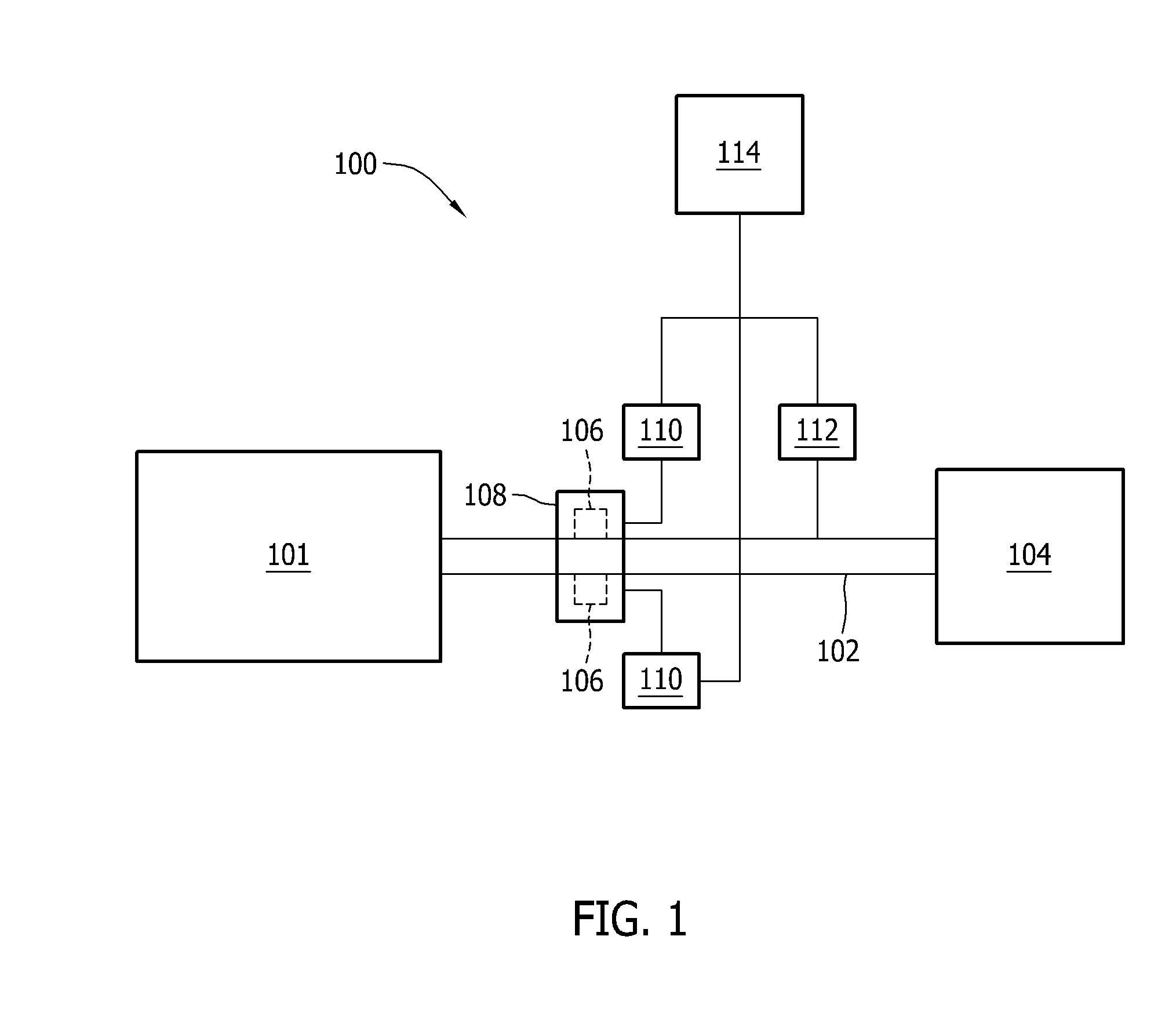
[0011]FIG. 1 illustrates an exemplary bearing monitoring system 100 that may be used to monitor a rotating machine 101. In the exemplary embodiment, machine 101 is a variable speed machine, such as a wind turbine, a hydroelectric generator, and / or any other rotating machine that operates with a variable speed. Alternatively, machine 101 may be a synchronous speed machine. In the exemplary embodiment, machine 101 drives a drive shaft 102 that is coupled to a load 104. Drive shaft 102 is at least partially supported by one or more bearings 106 housed within a support structure 108, such as a gearbox. Alternatively, bearings 106 may be housed within load 104, and / or within any suitable structure that enables bearings 106 to support drive shaft 102.

[0012]In the exemplary embodiment, bearings 106 are maintained in rotational contact with drive shaft 102 and support structure 108. If one or more bearings 106 develops a crack, spall, or any other defect, each of those bearings 106 may osci...


PUM


Abstract

A method of automatically detecting a rolling-element bearing fault in a rotating machine is provided. The method includes receiving, from at least one sensor, a sensor signal that includes at least one frequency, converting the sensor signal to a digital vibration signal, modifying the vibration signal to generate an envelope signal, and applying a transform to the enveloped signal to generate an envelope spectrum. The method uses certain relationships among envelope spectral line amplitudes and their harmonics to detect bearing faults. As such, the method detects a bearing fault without reference to predefined fault frequencies. Systems for implementing the method are also provided.

Description

BACKGROUND OF THE INVENTION[0001]The present application relates generally to rotating machines and, more particularly, to methods and systems for use in detecting rolling-element bearing faults in a rotating machine.[0002]At least some known power generation systems, such as wind turbines, include a generator that supplies electrical power to an electrical grid or to another power distribution system. Such generators are driven by a rotating drive shaft that is supported by bearings. A bearing monitoring system is sometimes used to monitor the bearings and / or other rotating elements.[0003]At least some known bearing monitoring systems execute an enveloping algorithm on an incoming signal, such as a vibration signal. More specifically, such algorithms enable identification of particular frequencies within the incoming signal that may suggest a bearing fault. The particular frequencies that suggest a bearing fault vary depending on the bearing, the power generation system, and other ...

Claims


Application Information

Patent Timeline
Patent Type & Authority Applications(United States)
IPC IPC(8): G06F19/00
CPCG01M13/045
Inventor HATCH, CHARLES TERRANCEWEISS, ADAM ANTHONYROALDSON, RYAN GREGORY
Owner GENERAL ELECTRIC CO
Why Eureka
Try Eureka