High range digital angular rate sensor based on frequency modulation

a digital angular rate sensor and frequency modulation technology, applied in the direction of acceleration measurement using interia force, turn-sensitive devices, instruments, etc., can solve the problem of imposing fundamental limitations on dynamic range and output stability, preventing mems gyroscopes from many potential applications, and reducing the gain-bandwidth tradeoff. , the effect of reducing the measurement bandwidth

Active Publication Date: 2013-04-25
RGT UNIV OF CALIFORNIA
View PDF23 Cites 39 Cited by
  • Summary
  • Abstract
  • Description
  • Claims
  • Application Information

AI Technical Summary

Benefits of technology

[0031]An angular rate sensor based on inherent Frequency Modulation (FM) free vibrations dynamics is disclosed that eliminates the gain-bandwidth tradeoff of conventional AM gyroscopes and enables signal-to-noise ratio improvements thought the use of ultrahigh Q structures without limiting the measurement bandwidth. At the same time, FM sensor architectures are known to be robust against mechanical and electromagnetic interferences. A differential frequency measurement enables simultaneous detection and decoupling of the input angular rate and the device temperature. In this approach, the gyroscope becomes its own thermometer, eliminating thermal lags and hysteresis common to conventional AM gyroscopes.

Problems solved by technology

These constraints stem from a fundamental Q versus bandwidth tradeoff and dynamic range limitations of analog Amplitude Modulation (AM) systems.
The first fundamental limitation of the described conventional architecture comes from the necessity to precisely measure extremely small analogue signals.
This imposes a fundamental limitation on the dynamic range and output stability and precludes MEMS gyroscopes from many potential applications.
While temperature compensation using an embedded thermometer is often used to reduce the effect of temperature, the approach limits the accuracy of the sensors and suffers from thermal hysteresis and lag.

Method used


Image

  • High range digital angular rate sensor based on frequency modulation
  • High range digital angular rate sensor based on frequency modulation
  • High range digital angular rate sensor based on frequency modulation

Examples


Embodiment Construction

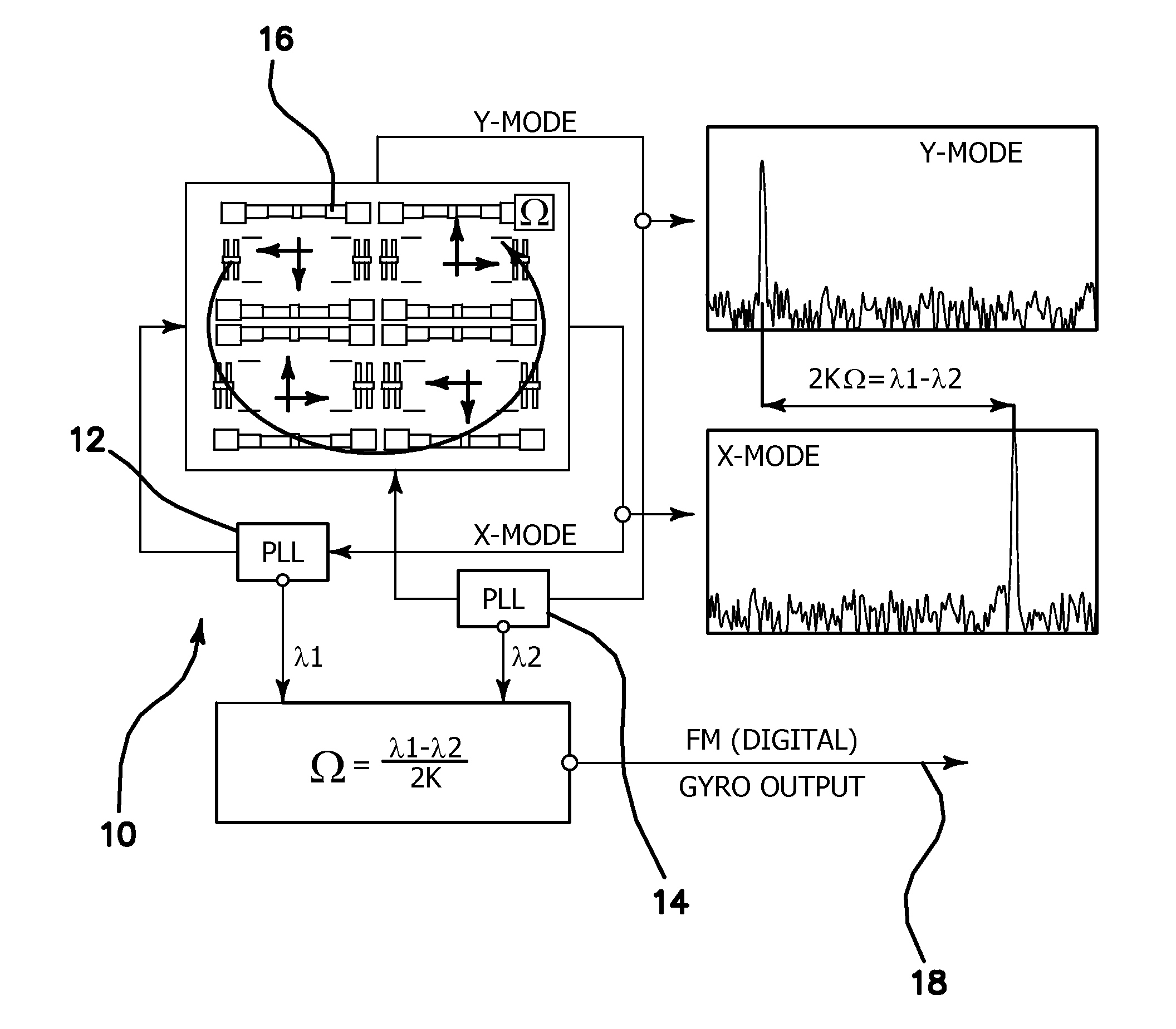
[0046]The illustrated embodiments address the following major limitations of conventional gyroscopes: analog output, narrow bandwidth and linear range, and temperature sensitivity. Currently these problems are solved by digitizing the inherently analog output signals (which increases the power consumption and degrades noise performance), lowering the quality factor (which degrades noise performance), and using a temperature sensor (which results in temperature lags and hysteresis), respectively.

[0047]The current invention comprises an FM gyroscope 16 with inherently digital output. Tradeoff between quality factor and range and bandwidth is eliminated, allowing the use of ultra-high Q for improved noise performance without limiting the bandwidth and range. Temperature is self-sensed and self-calibrated, so that hysteresis and lags are eliminated. In one embodiment, the invention can be used in any application requiring precise and stable detection of inertial rotation, including moti...


PUM


Abstract

A digital angular rate sensor system based on frequency modulation (FM) of the rotation rate. The new approach relies on tracking of the resonant frequencies of two high-Q mechanical modes of vibration in a MEMS vibratory gyroscope to produce an inherently digital measurement of the input angular rate. The disclosed system is enabled by a combination of a MEMS vibratory high-Q gyroscope and a new signal processing scheme which takes advantage of a previously ignored gyroscope dynamics effect. The FM nature of the system eliminates noise versus bandwidth and resolution versus dynamic range tradeoffs of conventional vibratory rate gyroscopes. The FM approach allows achieving superior signal-to-noise-ratio through the use of ultra-high Q (1 million) mechanical structure without limiting the measurement bandwidth. Stability of 1e-9 can be achieved in the FM system, providing a 1000 times improvement over the state-of-the-art conventional AM gyroscopes with capacitive pick-off.

Description

GOVERNMENT RIGHTS[0001]This invention was made with government support under Grant No. N00014-09-1-0424 awarded by the Office of Naval Research. The government has certain rights in the invention.BACKGROUND[0002]1. Field of the Technology[0003]The disclosure relates to the field of micromachined inertial sensors and gyroscopes, specifically high range digital angular rate sensors based on frequency modulation.[0004]2. Description of the Prior Art[0005]Vibratory gyroscopes have long be used in the art and maximization of their quality (Q) factors is key to improving performance. Mode matching of conventional high-Q angular rate gyroscopes increases the signal-to-noise ratio at the tradeoff of linear range and measurement bandwidth (10 deg / s range, sub-Hz bandwidth typical for Q˜100 k). These constraints stem from a fundamental Q versus bandwidth tradeoff and dynamic range limitations of analog Amplitude Modulation (AM) systems. In conventional Microelectromechanical Systems (MEMS) gy...

Claims


Application Information

Patent Timeline
Patent Type & Authority Applications(United States)
IPC IPC(8): G01C19/5607G01C19/56
CPCG01C19/5719
Inventor TRUSOV, ALEXANDERZOTOV, SERGEISHKEL, ANDREI
Owner RGT UNIV OF CALIFORNIA
Why Eureka
Try Eureka