Scanner Belt Load and Stretch Compensation Control System

a technology of belt load and stretch compensation, applied in the direction of optical radiation measurement, instruments, ways, etc., can solve problems such as sensor reading errors, and achieve the effect of reducing lead/lag error and loading becoming more uniform

Active Publication Date: 2013-04-25
HONEYWELL ASCA INC
View PDF19 Cites 23 Cited by
  • Summary
  • Abstract
  • Description
  • Claims
  • Application Information

AI Technical Summary

Benefits of technology

[0003]The movement of the upper and lower sensor head assemblies for a dual scanning system is typically driven independently by separate belt systems that are connected to a common drive shaft system. If both belt systems are equally tensioned and the mass and friction from both sensor head assemblies are equivalent then both upper and lower assemblies will move across the sheet in a synchronized manner, maintaining opposing positions. However, differences in mass, fric

Problems solved by technology

However, differences in mass, friction, and/or belt tension will manifest as an upper an

Method used


Image

  • Scanner Belt Load and Stretch Compensation Control System
  • Scanner Belt Load and Stretch Compensation Control System
  • Scanner Belt Load and Stretch Compensation Control System

Examples


Embodiment Construction

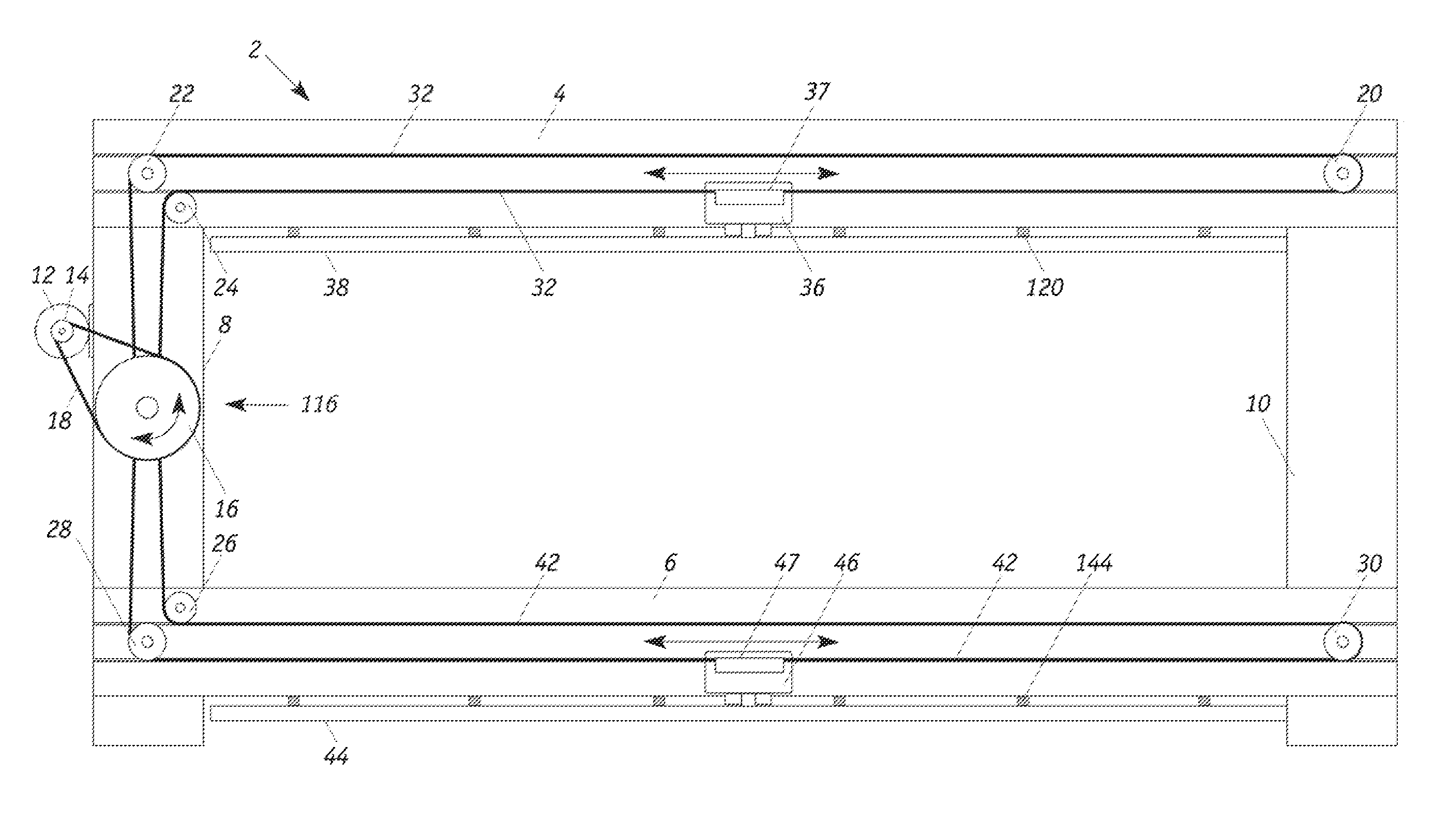
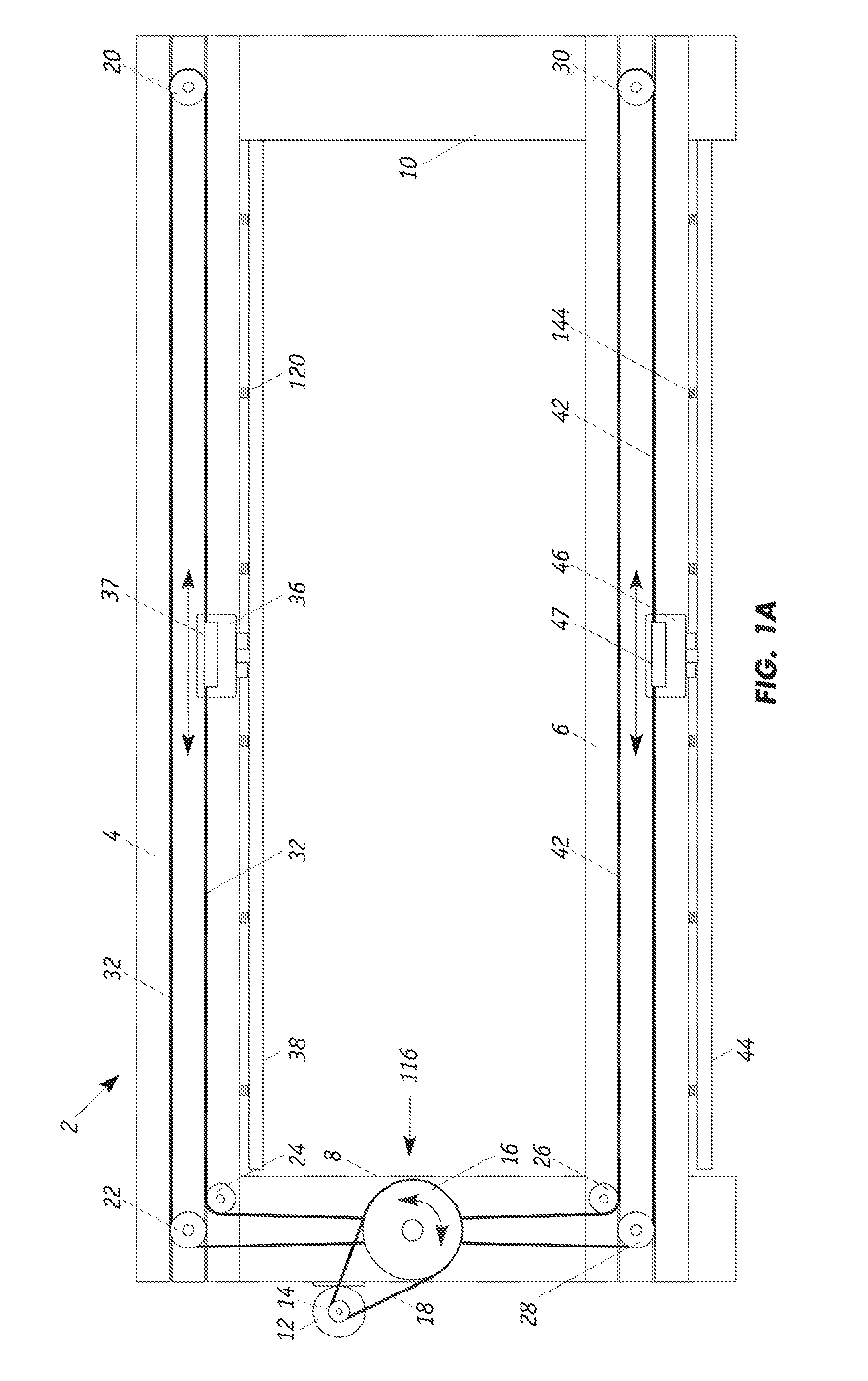
[0035]FIGS. 1A and 2 show a scanner frame system 2 that has upper and lower support beams 4, 6 that are mounted onto a pair of upright end members 8, 10. Associated upper and lower suspended tracks 38 and 44 are secured to the lower surfaces of upper and lower support beams 4 and 6, respectively. In particular, a series of upper individual vertical support structures 120 supports upper track 38 and a series of lower individual vertical support structures 144 supports lower track 44. As described further herein, each track defines a path along which a sensor-mounted roller carriage travels.

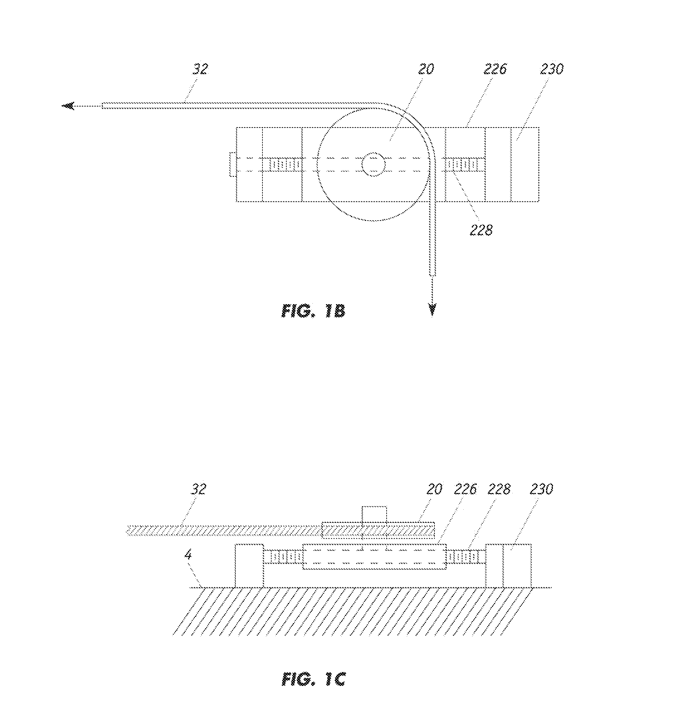
[0036]Upper support beam 4 is equipped with a plurality of upper fixed turning pulleys 20, 22 and 24 that are secured to the beam with pins. Each of the upper fixed turning pulleys preferably has a groove around its outer perimeter that is dimensioned to accommodate a flexible belt or cable 32 which is wound around the upper fixed turning pulleys and the proximal end 112 of drive shaft 110. Flexibl...


PUM


Abstract

Upper to lower assembly analog position sensors in a dual scanning system measure alignment offsets. A controller uses error signals from the position sensors to calculate actuator error profiles that are used in the next scan in the same direction, with different error profiles being used for forward and reverse scans. Since the alignment error profiles are repeatable for a given set of scanner conditions, the actuator controller anticipates what the error signal will be before each scanning assembly reaches a given position. An optimized error correction can be calculated based on the error profiles and actuator bandwidth without concerns regarding feedback loop speed, overshoot, and unstable control oscillations. An actuation system driven from error profiles can correct for alignment offsets by actively changing belt tensions at the offsetting drive pulleys and/or changing the position of sensor assemblies relative to the drive belt systems.

Description

FIELD OF THE INVENTION[0001]The present invention generally relates to scanner measurement systems for determining parameters of continuous sheet materials during production and, more particularly, to techniques for maintaining the alignment of dual scanner assemblies to achieve accurate measurement profiles.BACKGROUND OF THE INVENTION[0002]Various sensor systems have been developed for detecting sheet properties “on-line,” i.e., on a sheet-making machine while it is operating. Sensors for continuous flat sheet production processes typically employ single or dual-sided packages with on-line sensors that traverse or scan traveling webs of sheet material during manufacture. With dual scanners, the heads or assemblies are fixed to beams of a scanner frame system that span both sides of the sheet with linear guidance tracks to allow the sensors to move in unison in the cross direction, i.e., in the direction perpendicular to the direction of sheet-travel. Depending upon the sheet-making...

Claims


Application Information

Patent Timeline
IPC IPC(8): H04N1/04
CPCH04N2201/04753H04N2201/04755H04N1/053H04N2201/0471H04N1/203H04N1/128H04N2201/04734H04N2201/04794G01B2210/44
Inventor BESELT, RON
Owner HONEYWELL ASCA INC
Why Eureka
Try Eureka