Laterally expandable spinal prosthesis

a spinal prosthesis and lateral expansion technology, applied in the field of spinal prosthesis and orthopedic instruments, can solve the problems of reducing the height of the disc space affecting the function of the spinal disc, etc., and achieve the effect of increasing the width of the prosthesis

Active Publication Date: 2013-04-25
P&H MEDICAL PROD
View PDF5 Cites 92 Cited by
  • Summary
  • Abstract
  • Description
  • Claims
  • Application Information

AI Technical Summary

Benefits of technology

[0011]A method of implanting a spinal prosthesis within a patient is provided, including positioning a spinal prosthesis within an intervertebral space, the spinal prosthesis including a first portion and a second portion movably coupled to the first portion; and moving the second portion in a substantially posterior direction away from the first portion to increase a width of the prosthesis in an anterior-posterior direction. The method may include securing the position of the second portion relative to the first portion. Moving the second portion in a substantially posterior direction may be accomplished at least in part by mechanically actuating a gear interface of the prosthesis. The method may include introducing a biologic material into a cavity defined by the prosthesis. Positioning the spinal prosthesis may include directing the prosthesis into the intervertebral space in a substantially lateral-to-medial direction.

Problems solved by technology

However, the spinal discs may be displaced, damaged, or degraded due to trauma, disease or aging.
A herniated or ruptured annulus fibrosis may result in nerve damage, pain, numbness, muscle weakness, and even paralysis.
Furthermore, as a result of the normal aging processes, discs dehydrate and harden, thereby reducing the disc space height and producing instability of the spine and decreased mobility.
However, extensive vessel retraction is often required and many vertebral levels are not readily accessible from this approach.
However, difficulties remain in placing prostheses of sufficient size to stabilize the spinal segment while also adhering to or otherwise allowing reduced incisions for surgical access to the tissue site.
Moreover, the minimal size of the access can hamper accurate positioning of the prosthesis once inside the intervertebral space.

Method used


Image

  • Laterally expandable spinal prosthesis
  • Laterally expandable spinal prosthesis
  • Laterally expandable spinal prosthesis

Examples


Embodiment Construction

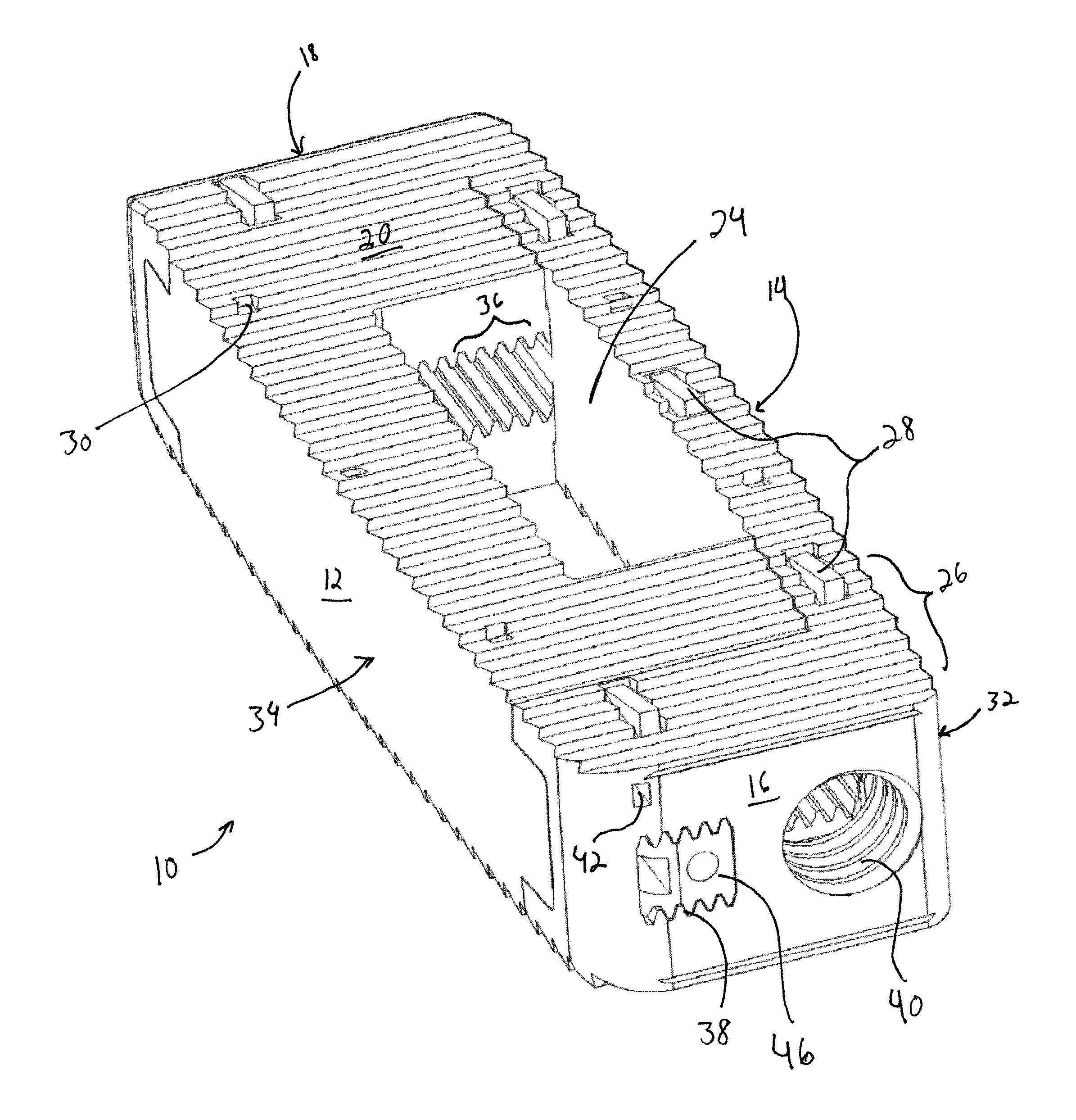
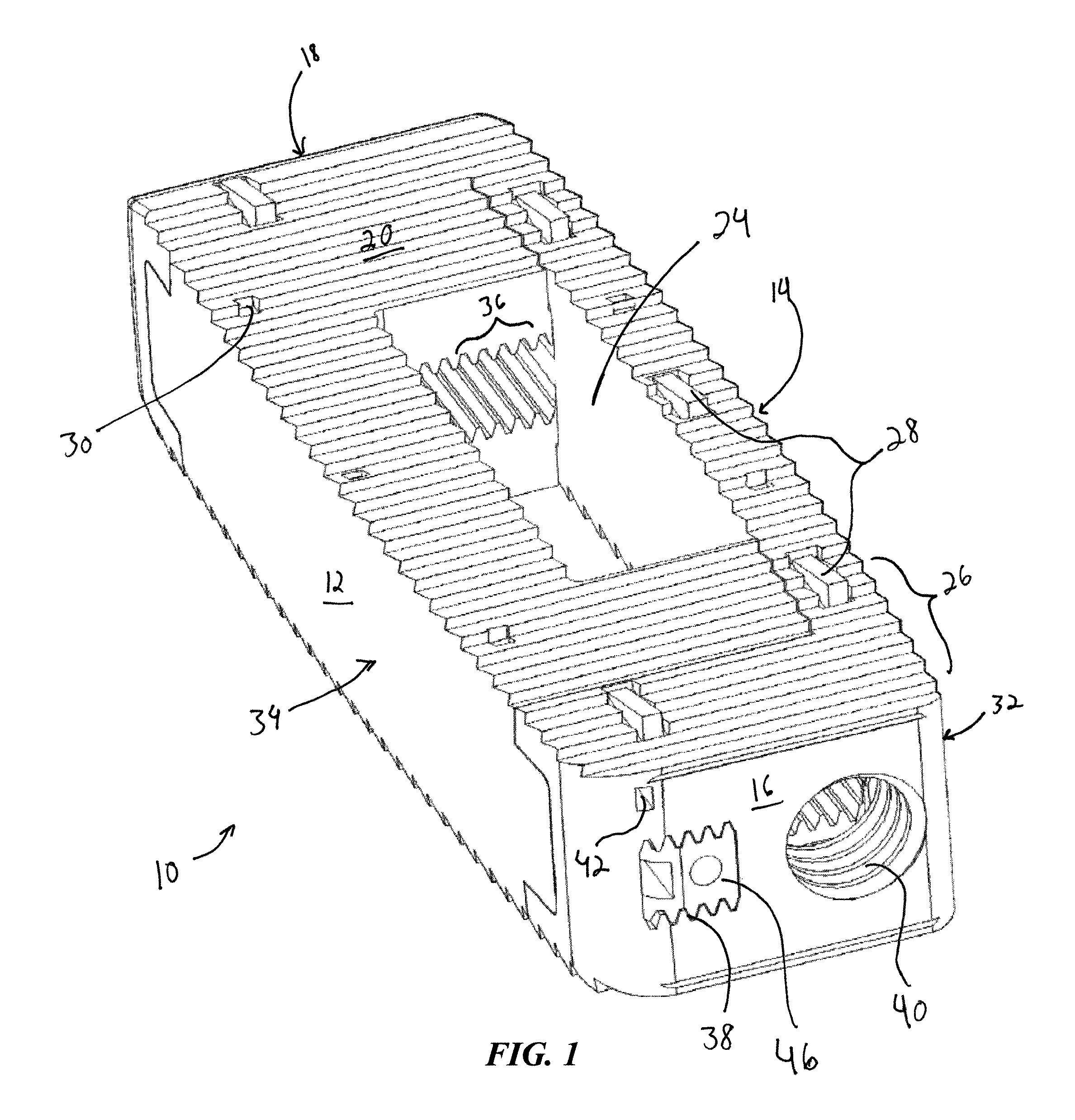
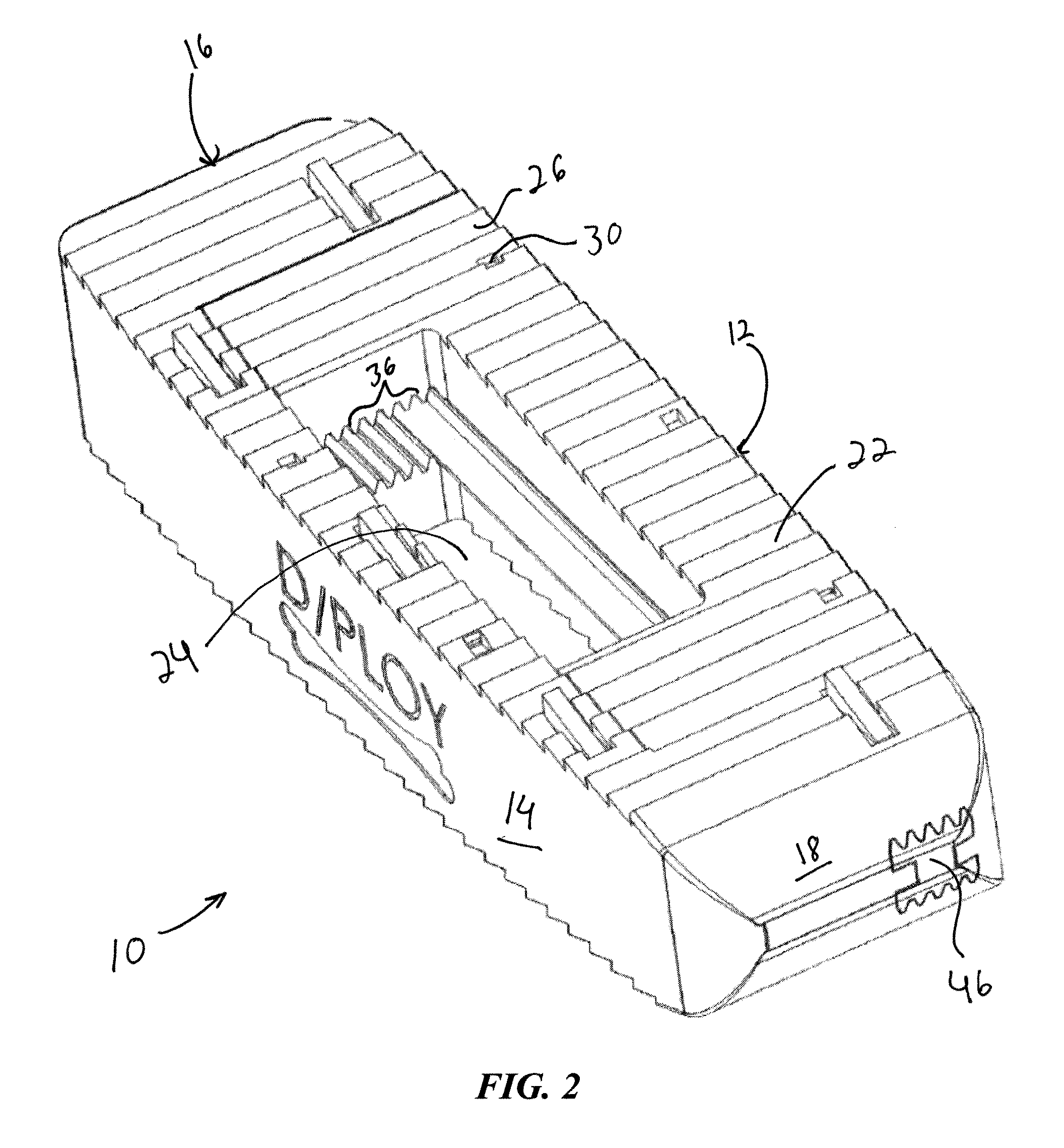
[0019]The present invention provides a prosthesis that can be easily inserted in accordance with a specific pathway or approach, such as a lateral approach, and that further eases obtaining a desired prosthesis position and resulting spinal segment stabilization. In particular, the prosthesis disclosed herein provides an adjustable, dynamic aspect ratio (i.e., the ratio of the width of the implant to its height) that can be adjusted to suit a varying range of surgical sites of different sizes in different patients. The adjustable size further allows a reduced, minimal profile during insertion while also allowing for expansion once positioned in a surgical site that may provide sufficient support and stabilization to negate a need for any additional posterior or anterior fusion hardware.

[0020]Now referring to FIGS. 1-2, a spinal prosthesis 10 is provided, where the spinal prosthesis 10 may include a prosthesis body generally defining a posterior wall 12, an anterior wall 14, a proxim...


PUM


Abstract

An expandable spinal prosthesis is disclosed, including a first surface having a first plurality of tissue anchors; a second surface opposite the first surface, the second surface having a second plurality of tissue anchors; a first wall between the first and second surfaces, and a second wall between the first and second surfaces, the second wall located opposite the first wall and being movable with respect to the first wall. A surgical instrument is also provided, including an elongated shaft defining a proximal end and a distal end; a first prosthesis engagement element accessible from the proximal end and extending from the distal end; and a second prosthesis engagement element accessible from the proximal end and extending from the distal end, the second prosthesis engagement element including a plurality of gear teeth.

Description

CROSS-REFERENCE TO RELATED APPLICATION[0001]This application is related to and claims priority to U.S. Provisional Patent Application Ser. No. 61 / 548,819, filed Oct. 19, 2011, entitled LATERALLY EXPANDABLE SPINAL PROSTHESIS, the entirety of which is incorporated herein by reference.STATEMENT REGARDING FEDERALLY SPONSORED RESEARCH OR DEVELOPMENT[0002]n / aFIELD OF THE INVENTION[0003]The present invention relates to spinal prostheses and orthopedic instrumentation and methods of use thereof.BACKGROUND OF THE INVENTION[0004]When healthy, intervertebral discs located between endplates of adjacent vertebrae stabilize the spine and distribute forces between the vertebrae and cushion vertebral bodies. However, the spinal discs may be displaced, damaged, or degraded due to trauma, disease or aging. A herniated or ruptured annulus fibrosis may result in nerve damage, pain, numbness, muscle weakness, and even paralysis. Furthermore, as a result of the normal aging processes, discs dehydrate and...

Claims


Application Information

Patent Timeline
Patent Type & Authority Applications(United States)
IPC IPC(8): A61F2/44
CPCA61F2002/30418A61F2002/30405A61F2002/30507A61F2002/30523A61F2002/30525A61F2002/30556A61F2002/30601A61F2002/3085A61F2002/30904A61F2002/4475A61F2002/4628A61F2002/4629A61F2/442A61F2/447A61F2/4611A61F2002/2817A61F2002/2835A61F2002/30393A61F2002/30401A61F2002/30476A61F2002/30593
Inventor PACKER, EVANHAY, J. SCOTT
Owner P&H MEDICAL PROD
Why Eureka
Try Eureka