
Component temperature control using a combination of proportional control valves and pulsed valves

a technology of proportional control valves and pulsed valves, applied in the direction of coatings, chemical vapor deposition coatings, lighting and heating apparatus, etc., can solve the problems of increasing the risk of mechanical failure in the system, frequent actuation of digital valve architectures, and limited lifetime of pressure waves

Active Publication Date: 2013-05-02
APPLIED MATERIALS INC
View PDF7 Cites 16 Cited by
  • Summary
  • Abstract
  • Description
  • Claims
  • Application Information

AI Technical Summary

Benefits of technology

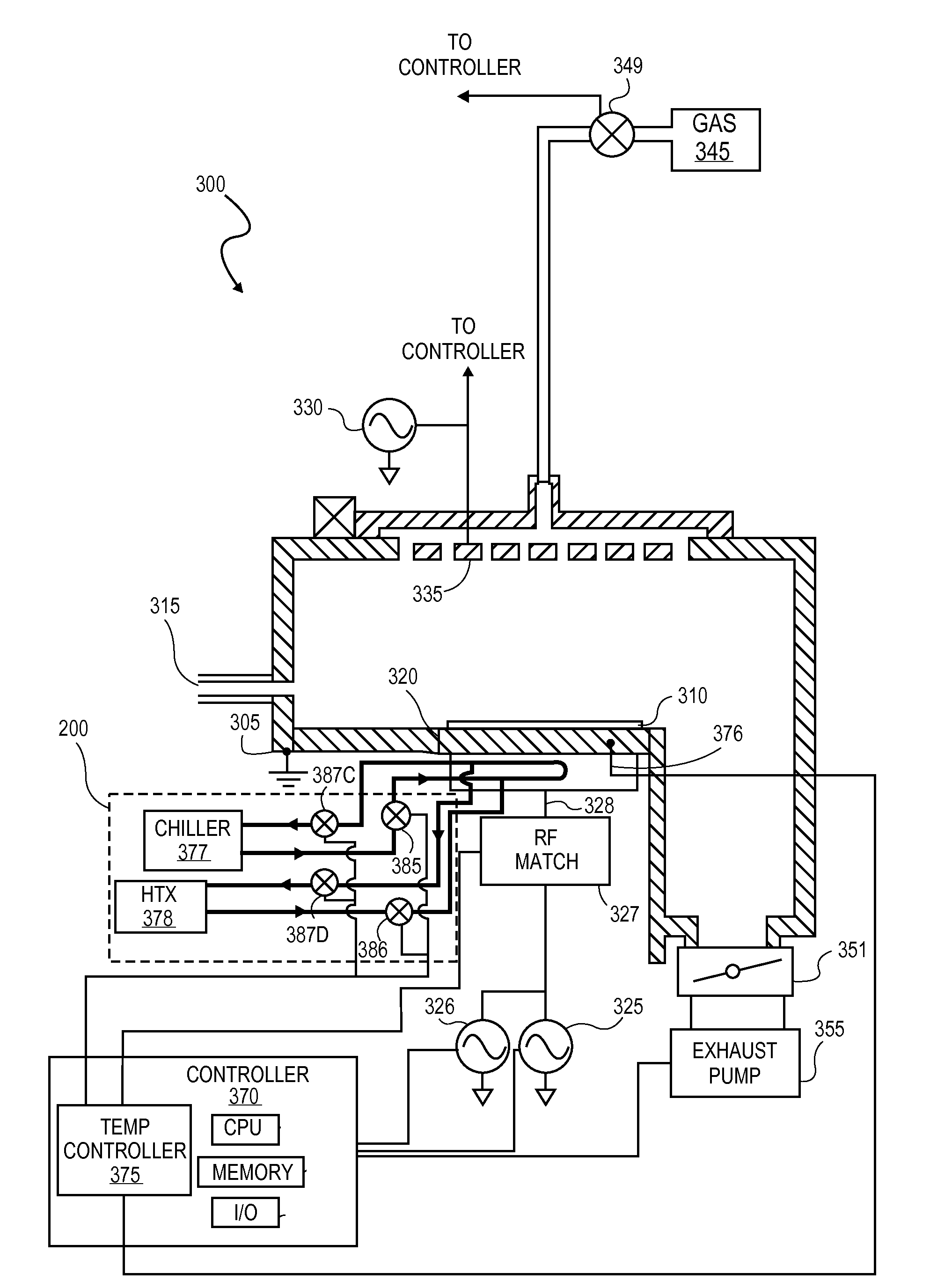
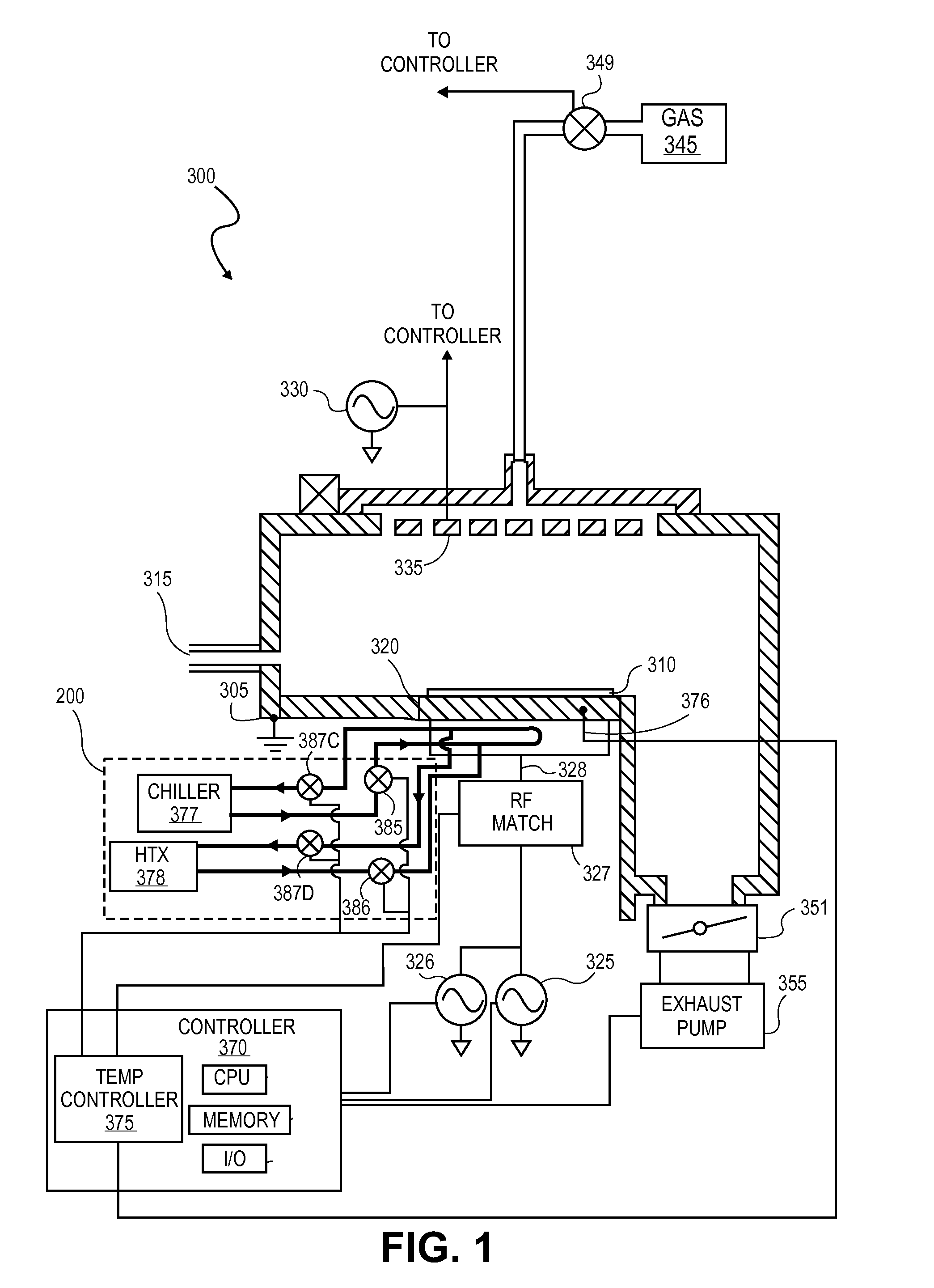
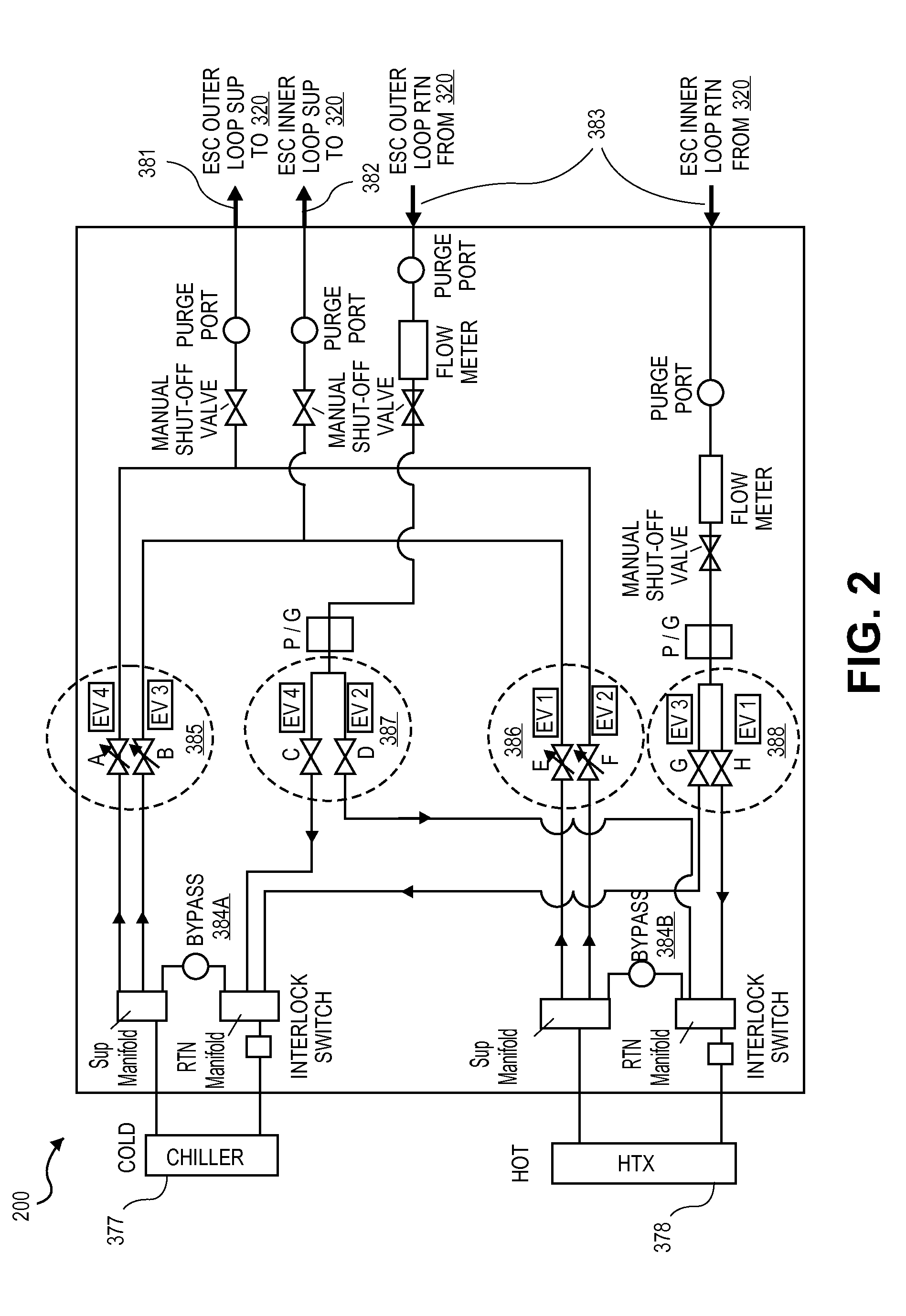
The patent describes a method for controlling the temperature in a plasma processing chamber using a combination of proportional and pulsed fluid control valves. The method involves using electronic control valves to control the fluid flow rate and to cycle the fluid between a heat source and a heat sink. The system includes multiple supply and return lines, each with an electronic control valve having a closed state, a partially open state, and a fully open state, to control fluid flow and temperature. The system also includes multiple heat transfer fluid reservoirs for different temperature zones. The technical effect of this patent is to provide a more precise and controlled method for controlling temperatures in plasma processing chambers, which can improve the quality and efficiency of the process.

Problems solved by technology

While economical, digital valve architectures may however be subject to frequent actuation and correspondingly limited lifetimes. Also, depending on liquid mass flow rates in the heating and cooling loops, abrupt valve closures may impart large momentum changes (i.e., fluid hammer) causing pressure waves increasing the risk of mechanical failures in the system.

Method used


Image

  • Component temperature control using a combination of proportional control valves and pulsed valves
  • Component temperature control using a combination of proportional control valves and pulsed valves
  • Component temperature control using a combination of proportional control valves and pulsed valves

Examples


Embodiment Construction

[0017]In the following detailed description, numerous specific details are set forth in order to provide a thorough understanding of embodiments of the invention. However, it will be understood by those skilled in the art that other embodiments may be practiced without these specific details. In other instances, well-known methods, procedures, components and circuits have not been described in detail so as not to obscure the present invention. Some portions of the detailed description that follows are presented in terms of algorithms and symbolic representations of operations on data bits or binary digital signals within a computer memory.

[0018]Unless specifically stated otherwise, as apparent from the following discussions, it is appreciated that throughout the specification discussions utilizing terms such as “processing,”“computing,”“calculating,”“determining,” or the like, refer to the action and / or processes of a computer or computing system, or similar electronic computing dev...


PUM

PropertyMeasurementUnit
Temperatureaaaaaaaaaa

Abstract

Methods and systems for controlling temperatures in plasma processing chamber with a combination of proportional and pulsed fluid control valves. A heat transfer fluid loop is thermally coupled to a chamber component, such as a chuck. The heat transfer fluid loop includes a supply line and a return line to each of hot and cold fluid reservoirs. In an embodiment, an analog valve (e.g., in the supply line) is controlled between any of a closed state, a partially open state, and a fully open state based on a temperature control loop while a digital valve (e.g., in the return line) is controlled to either a closed state and a fully open state.

Description

CROSS-REFERENCE TO RELATED APPLICATIONS[0001]This application claims the benefit of U.S. Provisional Application No. 61 / 552,352 filed on Oct. 27, 2011 titled “ESC TEMPERATURE CONTROL USING A COMBINATION OF PROPORTIONAL CONTROL VALVES AND PULSED VALVES,” the content of which is hereby incorporated by reference in its entirety for all purposes.[0002]This application is related to U.S. Utility application Ser. No. 13 / 111,334 filed on May 19, 2011, titled “TEMPERATURE CONTROL IN PLASMA PROCESSING APPARATUS USING PULSED HEAT TRANSFER FLUID FLOW,” and U.S. Utility application Ser. No. 13 / 040,149 filed on Mar. 3, 2011, titled “COMPONENT TEMPERATURE CONTROL BY COOLANT FLOW CONTROL AND HEATER DUTY CYCLE CONTROL.TECHNICAL FIELD[0003]Embodiments of the present invention generally relate to plasma processing equipment, and more particularly to methods of controlling chamber component temperatures during processing of a workpiece with a plasma processing chamber.BACKGROUND[0004]In a plasma proce...

Claims


Application Information

Patent Timeline
IPC IPC(8): C23F1/08F28F27/02
CPCH01L21/67109C23C16/4586C23C16/46C23C16/463H01L21/67248
Inventor MAHADESWARASWAMY, CHETAN
Owner APPLIED MATERIALS INC
Learn More