Fuel Tank with Separating Membrane

a technology of separating membrane and fuel tank, which is applied in the direction of special purpose vessels, container discharging methods, transportation items, etc., can solve the problems of insufficiently solved creeping of the membrane at the clamping arrangement, inability to meet the requirements of space flight liquid compatibility, and inability to manufacture elastomer membrane materials. to achieve the effect of high chemical compatibility of the separating membran

Active Publication Date: 2013-05-02
ASTRIUM GMBH
View PDF16 Cites 4 Cited by
  • Summary
  • Abstract
  • Description
  • Claims
  • Application Information

AI Technical Summary

Benefits of technology

The invention is a tank for storing various liquids, including fuel and oxidizers used in propulsion systems. The tank has a membrane that can withstand high levels of chemical compatibility, making it suitable for a wide range of liquids. Additionally, the tank has a spring ring that is designed to prevent the membrane from slipping out of the recess and a roughened surface to improve its performance. The technical effects of this invention are a universal tank design that can be used for fuel and oxidizers, as well as for other aggressive liquids.

Problems solved by technology

However, elastomer membrane materials having a sufficient compatibility with the liquids used in space flight are not available, because such liquids are chemically very aggressive, such as the oxidizer types based on nitrogen dioxide.
Thus, elastomer membranes are not suitable for membrane tanks for use in space flight systems.
These, however, are of a plastic nature, and as plastic materials are not suitable for a direct clamping-in inside the tank, because they lack an inherent durable stable resilient restoring force.
The mechanical problems arising in the use of plastic polymer materials for tank separating membranes are as follows:1.) tear formation during the inversion process,2.) permeation and leaking through pores, especially with thin-walled materials,3.) creeping under the influence of pressure forces with the result of an attachment that is not durably secure over time, and a merely temporary leak-tightness of the membrane clamping arrangement.< /
While the first two problems can be regarded as already having been solved in the known tanks that are being used today, the problem of the creeping of the membrane at the clamping arrangement has previously still not been satisfactorily solved.

Method used


Image

  • Fuel Tank with Separating Membrane
  • Fuel Tank with Separating Membrane

Examples


Embodiment Construction

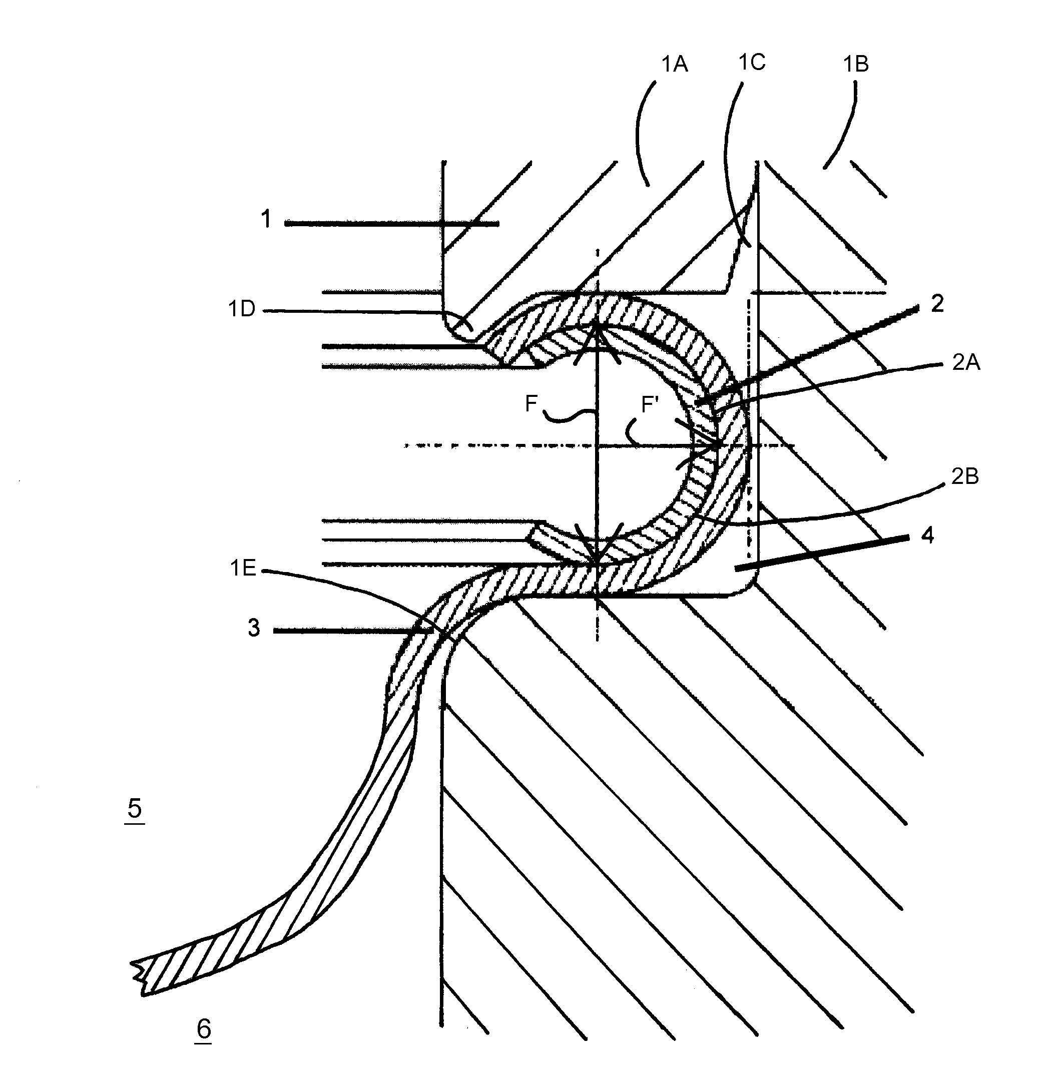
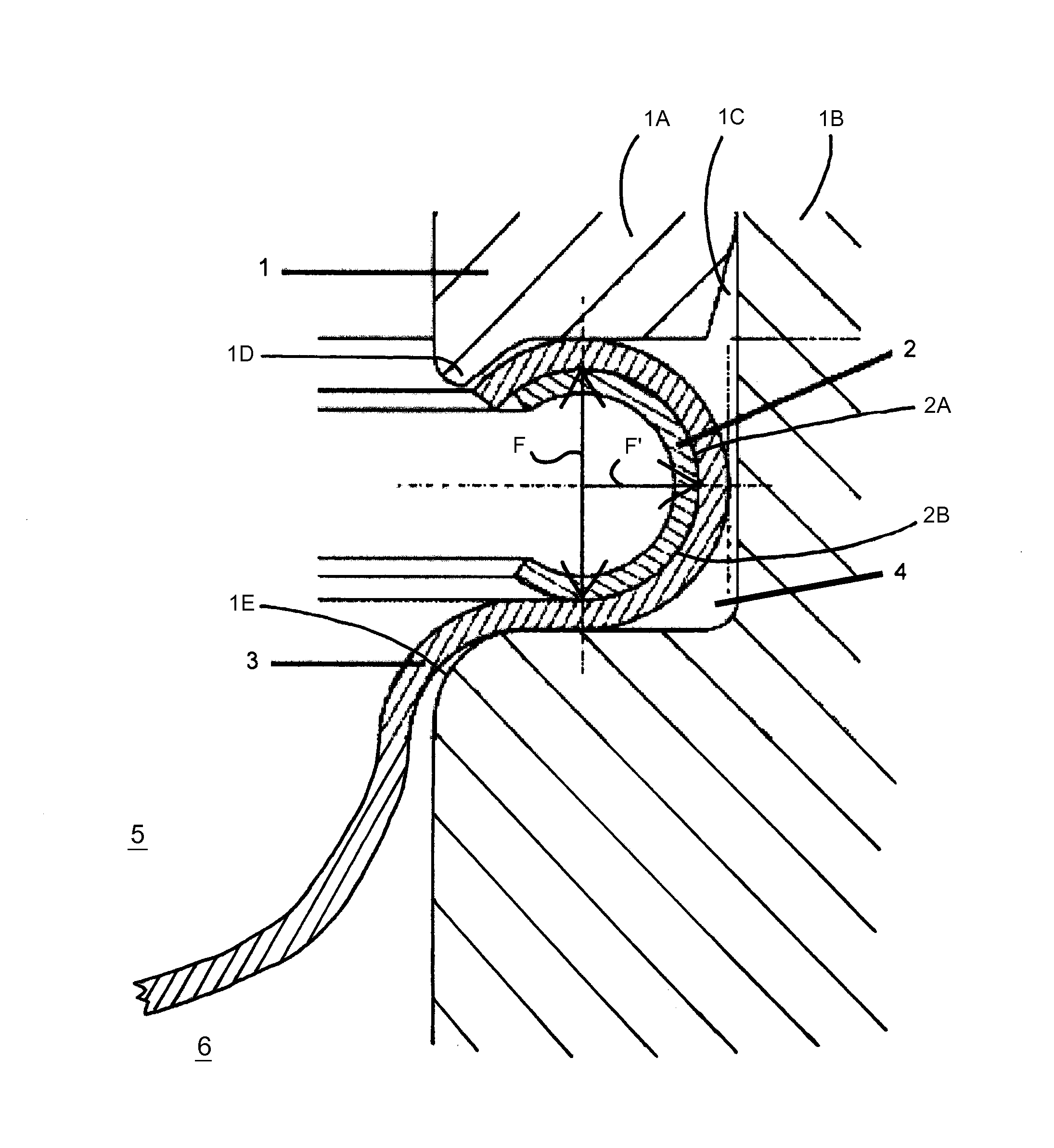
[0022]In the following, an arrangement according to the invention will be described in more detail in connection with a schematically illustrated example embodiment.

[0023]In a partially sectioned illustration, a tank wall 1 is illustrated, with a polymer membrane 3 clamped into a corresponding recess 4 of a tank wall 1 by a spring ring 2, which comprises a cross-section in the shape of a “C”. The spring ring 2 is preferably made of a metal alloy that has an elastic spring characteristic. Especially when the spring ring 2 is to be exposed to the rocket fuel or oxidizer liquid in the liquid space 5 on one side of the membrane 3, then the spring ring 2 is preferably made of a metal alloy material that is chemically compatible with or inert and resistant to the chemical composition of the rocket fuel or oxidizer.

[0024]The C-shape of the spring ring 2 refers to the sectional shape of the spring ring as shown in the drawing FIGURE, but in a view direction perpendicular to the view directi...


PUM


Abstract

A tank especially suitable for use as a fuel or oxidizer tank in spacecraft is divided into two tank spaces by a membrane. A liquid is stored on one side of the membrane and a pressure gas is stored on the other side of the membrane. The pressure gas is to drive the liquid out of the tank. The membrane is made of a polymer material and is held by a spring ring in a recess on the outer wall of the tank. The spring ring has a substantially C-shaped cross-section to exert elastic spring holding forces on the membrane in the recess.

Description

PRIORITY CLAIM[0001]This application is based on and claims the priority under 35 USC 119 of German Patent Application DE 10 2011 117 489.7, filed on 27 Oct. 2011, the entire disclosure of which is incorporated herein by reference.FIELD OF THE INVENTION[0002]The invention relates to a fuel tank for the storage of liquids, which are driven out of the tank by a pressure gas, especially for use in spacecraft. The tank is constructed as a membrane tank and in which the membrane consists of a synthetic material.BACKGROUND INFORMATION[0003]Membrane tanks are preferably used as containers for the storage of liquids, especially for the storage of fuels, which are impinged upon and pressurized by a pressure gas that is separated from the respective liquid by a separating membrane in the tank. Such uses typically arise in space travel under conditions of weightlessness, but also under gravity, for example in rapidly or strongly position-variable systems, such as aircraft or submarines. While ...

Claims


Application Information

Patent Timeline
Patent Type & Authority Applications(United States)
IPC IPC(8): B64G1/22
CPCB64G1/402F17C2270/0197F17C1/00F15B1/125F17C2201/0128F17C2201/0185F17C2201/056F17C2223/0153F17C2223/0161F17C2223/035F17C2227/0192F17C2260/027F17C2260/05F17C2270/0131F17C2270/0189F17C2270/0194F17C2221/08F17C7/00B64G1/4021
Inventor SCHWARTING, WALTERGOEK, SYLVAIN
Owner ASTRIUM GMBH
Why Eureka
Try Eureka