Low cost metal bipolar plates and current collectors for polymer electrolyte membrane fuel cells

a fuel cell and current collector technology, applied in the field of low cost metal bipolar plates and current collectors for polymer electrolyte membrane fuel cells and fuel cell stacks, can solve the problems of high cost and low power density of the fuel cell system, high cost of graphite, and high cos

Inactive Publication Date: 2004-04-20
GAS TECH INST
View PDF6 Cites 12 Cited by
  • Summary
  • Abstract
  • Description
  • Claims
  • Application Information

AI Technical Summary

Benefits of technology

It is another object of this invention to provide a metal bipolar plate for polymer electrolyte membrane fuel cell stacks which is chemically stable in the polymer electrolyte membrane fuel cell environment and which does not require application of a protective coating.
It is another object of this invention to provide a metal bipolar plate for polymer electrolyte membrane fuel cell stacks which has good chemical compatibility with other components of the fuel cell stack.

Problems solved by technology

Substantial drawbacks to widespread acceptance and implementation of polymer electrolyte membrane fuel cell systems as a power source for transportation applications are the high costs and the low power density of the fuel cell systems.
On the negative side, graphite is high in cost, difficult to machine and brittle, the latter problem requiring that the bipolar plates have a thickness on the order of several millimeters, making the fuel cell stack both heavy and voluminous.
However, as a general rule, metal plates have a high corrosion rate in the polymer electrolyte membrane fuel cell environment, resulting in the migration of corrosion products (multivalent metal cations) to membrane sites and a reduction in proton transfer rate.
Noble metals are viable candidates but are very expensive.
However, stainless steel is chemically unstable in the fuel cell environment.
It has a high corrosion current when in contact with the acidic electrolytic membrane in the operation region of the fuel cell and it cannot work if the pH is less than 5.
However, this requires an extra processing step and adds both cost and weight to the plate and, thus, the fuel cell stack.

Method used


Image

  • Low cost metal bipolar plates and current collectors for polymer electrolyte membrane fuel cells
  • Low cost metal bipolar plates and current collectors for polymer electrolyte membrane fuel cells

Examples


Embodiment Construction

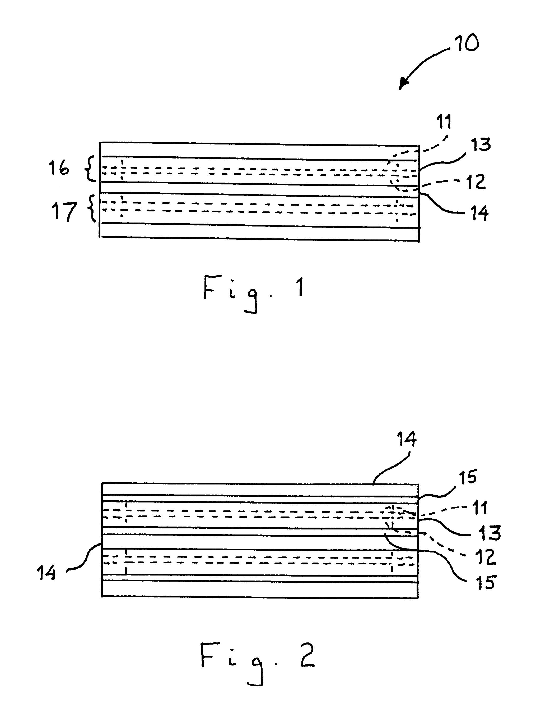
As shown in FIG. 1, a polymer electrolyte membrane fuel cell stack 10 in accordance with one embodiment of this invention comprises a plurality of polymer electrolyte membrane fuel cell units 16, 17 comprising anode electrode 11, cathode electrode 12 and polymer electrolyte membrane 13 disposed between anode electrode 11 and cathode electrode 12. Frequently, the anode electrode, polymer electrolyte membrane and cathode electrode are formed as a single component referred to as a membrane electrode assembly or MEA. Disposed between cathode electrode 12 of one fuel cell unit 16 and anode electrode 11 of an adjacent fuel cell unit 17 is bipolar separator plate 14. In accordance with one embodiment of this invention, bipolar separator plate 14 comprises a chromium-nickel austenitic metal alloy in which the amount of chromium and nickel on a combined basis is greater than about 50% by weight of the alloy.

In operation, a fuel is introduced into the anode side of the polymer electrolyte mem...


PUM

PropertyMeasurementUnit
areaaaaaaaaaaa
pHaaaaaaaaaa
pHaaaaaaaaaa

Abstract

A polymer electrolyte membrane fuel cell stack having a plurality of substantially planar fuel cell units, each of which comprises an anode electrode, a cathode electrode and a polymer electrolyte membrane disposed between the anode electrode and the cathode electrode. A metal bipolar plate is disposed between the anode electrode of one fuel cell unit and the cathode electrode of an adjacent fuel cell unit. The metal bipolar plate is made of a chromium-nickel austenitic alloy, in which the chromium and the nickel, on a combined basis, make up at least about 50% by weight of the alloy.

Description

1. Field of the InventionThis invention relates to polymer electrolyte membrane fuel cells, polymer electrolyte membrane fuel cell stacks, and, in particular, low cost metal bipolar plates and current collectors for polymer electrolyte membrane fuel cells and fuel cell stacks.2. Description of Prior ArtA polymer electrolyte membrane fuel cell is an electrochemical device capable of producing electricity (and chemical compounds), which is a promising option as a power source for electrical vehicles. Polymer electrolyte membrane fuel cells comprise an anode electrode, a cathode electrode and a polymer electrolyte membrane disposed therebetween. To provide sufficient electrical output, individual fuel cell units are stacked, one on top of the other, with electrically conductive bipolar plates disposed between the anode electrode of one fuel cell unit and the cathode electrode of an adjacent fuel cell unit.Substantial drawbacks to widespread acceptance and implementation of polymer elec...

Claims


Application Information

Patent Timeline
Patent Type & Authority Patents(United States)
IPC IPC(8): H01M8/02
CPCH01M8/021H01M8/0213H01M8/0247Y02E60/50
Inventor FAN, QINBAICHERVINKO, JEREMY R.ONISCHAK, MICHAELMARIANOWSKI, LEONARD G.
Owner GAS TECH INST
Why Eureka
Try Eureka