Oxide-forming protective coatigns for niobium-based materials

a technology of niobium-based materials and protective coatings, applied in the field of coatings, can solve the problems of inability to meet the requirements of nb-based alloys and rmics, and inability to achieve sustained formation of alumina scale, etc., and achieve the effect of promoting the oxidation resistance of the substra

Active Publication Date: 2011-06-23
GENERAL ELECTRIC CO
View PDF10 Cites 11 Cited by
  • Summary
  • Abstract
  • Description
  • Claims
  • Application Information

AI Technical Summary

Benefits of technology

[0012]According to still another aspect of the invention, a gas turbine engine component is provided having a substrate formed of a niobium-based material, such as a monolithic niobium-based alloy or a niobium-based composite material. A coating formed of one of the two above-noted compositions is provided on the substrate surface to promote the oxidation resistance of the substrate. Finally, an oxide scale is present on a surface of the coating.

Problems solved by technology

However, a significant impediment to the development of Nb-based alloys and RMICs for high-temperature applications in aircraft engines is their oxidation resistance.
However, the sustained formation of alumina scale has not been achieved in these attempts, and to date aluminum-based coatings suitable for protecting Nb alloys has not been practical.
Another result of the interdiffusion process used to form Si—Cr—Ti or Si—Cr—Fe coatings is that a significant number of vertical cracks form in the coating, often in excess of one hundred vertical cracks per inch, when formed on Nb—Si composites.
Oxides that form in the vertical cracks during high temperature exposure cause the cracks to wedge open, increasing the depth of the cracks into the substrate.
Ultimately, the coating spalls because the crack-opening effect caused by oxidation exposes the substrate material directly to the oxidative environment.

Method used


Image

  • Oxide-forming protective coatigns for niobium-based materials
  • Oxide-forming protective coatigns for niobium-based materials
  • Oxide-forming protective coatigns for niobium-based materials

Examples


Embodiment Construction

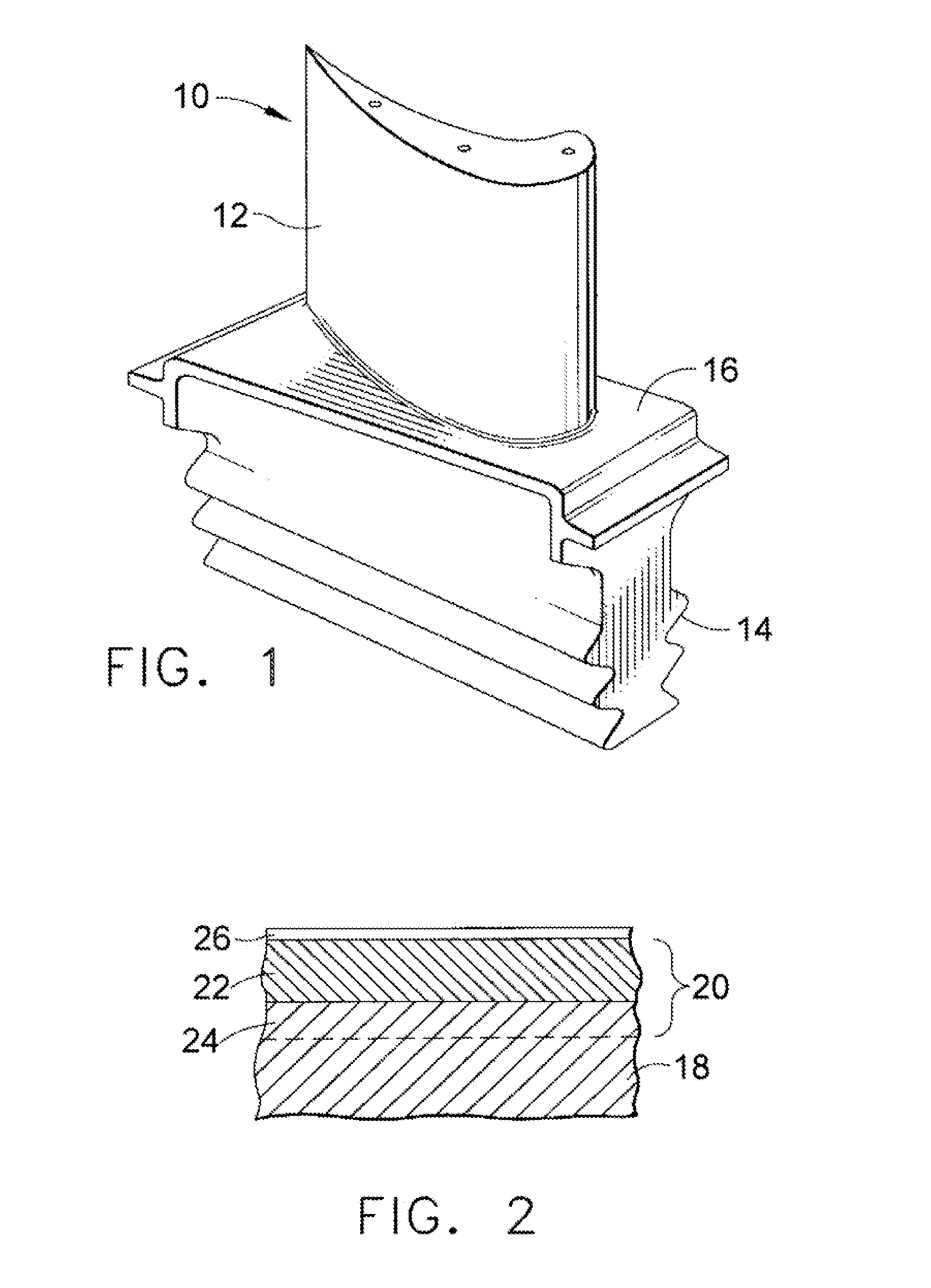
[0022]The present invention is generally applicable to components that operate within environments characterized by relatively high temperatures and subjected to severe oxidation. Notable examples of such components include blades, nozzles, vanes, shrouds, afterburner components, and other components within the hot gas flow path of gas turbine engines. One such example is the high pressure turbine blade 10 shown in FIG. 1. The blade 10, which is typically in the form of a casting, generally includes an airfoil 12 against which hot combustion gases are directed during operation of the gas turbine engine, and whose surface is therefore subjected to severe attack by oxidation, corrosion and erosion. A platform 16 separates the airfoil 12 from a dovetail 14 formed on a root section of the blade 10, by which the airfoil 12 is anchored to a turbine disk (not shown). While the advantages of this invention will be described with reference to the turbine blade 10 shown in FIG. 1, the teachin...


PUM

PropertyMeasurementUnit
oxidation resistanceaaaaaaaaaa
compositionaaaaaaaaaa
temperatureaaaaaaaaaa

Abstract

Coatings suitable for use as protective oxide-forming coatings on Nb-based substrates exposed to high temperatures and oxidative environments. The coatings contain chromium and/or molybdenum, preferably contains silicon, and optionally contains niobium, titanium, hafnium, iron, rhenium, tantalum, and/or tungsten, which in combination form multiple intermetallic phases, which in combination form one or more intermetallic phases that promote the formation of a slow-growing oxide scale. Depending on the particular coating composition, the intermetallic phases may be: a silicon-modified Cr2Nb Laves phase and optionally a chromium solid solution phase, a CrNbSi intermetallic phase, and/or an M3Si intermetallic phase where M is niobium, titanium, and/or chromium; or M5Si3, MSi2 and/or M3Si2 where M is molybdenum, niobium, titanium, chromium, hafnium, iron, rhenium, tantalum, and/or tungsten.

Description

BACKGROUND OF THE INVENTION[0001]This invention generally relates to coatings suitable for protecting components exposed to high-temperature environments, such as the hot gas flow path through a gas turbine engine. More particularly, this invention is directed to coatings that impart oxidation resistance to niobium-based materials, including niobium-based alloys and niobium-silicide composites.[0002]Higher operating temperatures for gas turbine engines are continuously sought in order to increase their efficiency. While nickel, cobalt and iron-base superalloys have found wide use for components within the hot sections of gas turbine engines, alternative materials have been proposed to achieve improved high-temperature properties. For example, refractory metal alloys and intermetallic materials have been proposed as candidates for high temperature applications, such as blades, nozzles, vanes, shrouds, afterburner components, and other hot gas path components of gas turbine engines. E...

Claims


Application Information

Patent Timeline
Patent Type & Authority Applications(United States)
IPC IPC(8): C22C27/02B22F7/02C22C27/06C23C16/00B32B3/10B32B15/01
CPCB32B15/01Y10T428/12611C22C27/06C22C30/00C23C10/28C23C14/0682C23C14/5806C23C30/00F01D5/286Y02T50/67Y02T50/672F05D2230/90F05D2260/95F05D2300/502Y10T428/12819Y10T428/12361C22C27/02C23C10/26Y02T50/60
Inventor BEWLAY, BERNARD PATRICKSUBRAMANIAN, PAZHAYANNUR RAMANATHANRIGNEY, JOSEPH DAVIDDIDOMIZIO, RICHARDDHEERADHADA, VORAMON SUPATARAWANICH
Owner GENERAL ELECTRIC CO
Why Eureka
Try Eureka