Traffic signal light device

Active Publication Date: 2013-05-02
LEOTEK CORP
View PDF9 Cites 16 Cited by
  • Summary
  • Abstract
  • Description
  • Claims
  • Application Information

AI Technical Summary

Benefits of technology

[0008]Accordingly, one objective of the present invention is to provide an optical lens design that can efficiently couple the light from the high power LED to the asymmetrical Fresnel lens and then to the spreading lens for the desired light dist

Problems solved by technology

However, for certain applications, such as traffic signal lights, the use of high power LEDs have been somewhat hampered because their light distribution pattern is not readily compatible with the asymmetric light distribution pattern required for traffic signal lights.
This pre

Method used


Image

  • Traffic signal light device
  • Traffic signal light device
  • Traffic signal light device

Examples


Example

[0044]According to first embodiment of LED lens 122 as shown in FIG. 6B, the LED lens 122 comprises a first portion 1221 and a second portion 1222, wherein the first portion 1221 and the second portion 1222 are asymmetric for providing an asymmetric light emitting profile as shown in FIG. 6B. In this embodiment, the light intensity near the center is smaller than that near the sides, and the light intensities at two sides are different.

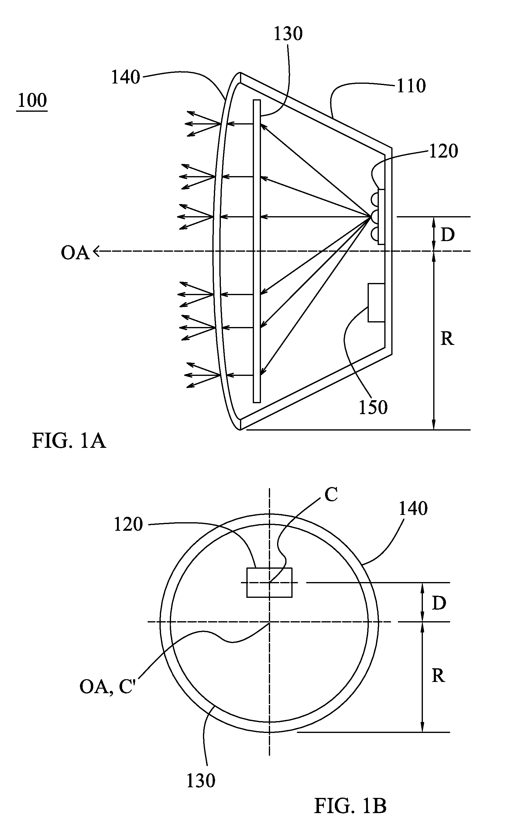
[0045]The embodiment of LED lens 122 in FIG. 6B can be used in the traffic signal light device provided in the present invention, wherein the LED module is disposed to be offset from the center of the spread window. In FIG. 1A, the LED module 120 is disposed at upper side of the optical axis OA. Therefore, in order to get uniform illumination on the Fresnel lens 130, the light emitting profile of the LED module 120 is asymmetric as shown in FIG. 6B. More specifically, the light intensity at the upper side of the LED module 120 is smaller than that at ...

Example

[0046]According to a second embodiment of LED lens 122 as shown in FIG. 6C, the LED lens 122 comprises a first portion 1221 and a second portion 1222, wherein the first portion 1221 and the second portion 1222 are symmetric for providing symmetric light emitting profile as shown in FIG. 6C. In this embodiment, the light intensity near the center is smaller than that near the sides.

Example

[0047]Both of the first and the second embodiments of the LED lens in FIGS. 6B and 6C can provide uniform illumination on the illumination area.

[0048]FIG. 7A shows a schematic view of an indicating signal shape of the traffic signal (i.e. the traffic signal includes a mask which is selectively light transmissive only for those portions within the indicating signal shape). FIG. 7B shows a schematic view of an LED lens 122 having a shape related to the indicating signal shape according to a third embodiment of the LED lens.

[0049]The traffic signal may have a special indicating shape, for example, an arrow shape for indicating directions as shown in FIG. 7A. In this case, the LED light still illuminates on the whole signal area (the whole round area). However, only the LED light illuminating on the arrow shape can be emitted out, and the other LED light is blocked from forming the arrow-shaped indication. Therefore, the light energy of the LED light is wasted.


PUM


Abstract

A traffic signal light device that includes a spread window, a Fresnel lens, and an LED module for emitting light. The light emitted by the LED module passes through the Fresnel lens and to the spread window. The LED module is disposed at a position that is offset from an axis of the spread window that passes through a center of, and is perpendicular to, the spread window. The Fresnel lens can have a saw-toothed pattern of teeth formed as concentric circles on one surface of the Fresnel lens sharing a common center, where the size or height of the teeth vary. The spread window can have a plurality of protruding cells of varying size on a surface of the spread window.

Description

RELATED APPLICATIONS[0001]This application claims the benefit of U.S. Provisional Application No. 61 / 551,156, filed Oct. 25, 2011, and which is incorporated herein by reference.BACKGROUND OF THE INVENTION[0002]1. Field of the Invention[0003]The present invention relates in general to a traffic signal light device, and more in particular to the traffic signal light device using high power Light-Emitting Diodes (LEDs).[0004]2. Description of the Related Art[0005]Light-Emitting Diodes (LEDs) have been used in many applications to replace the conventional incandescent lamps, fluorescent lamps, Neon tube and fiber optics light sources to reduce electrical cost, maintenance cost and increase reliability. Due to the fact that LEDs consume less electrical energy than conventional light sources while exhibiting much longer lifetime, many designs have been invented for various applications, such as traffic signal lights, channel letters, conventional illuminated commercial signs, street light...

Claims


Application Information

Patent Timeline
IPC IPC(8): F21V5/04F21V13/04
CPCF21V5/045F21V13/04F21V5/02F21W2111/00F21W2131/103F21Y2101/02G02B19/0061B61L5/1854F21V5/08G02B3/08F21W2111/02G02B19/0014F21Y2105/001F21Y2105/10F21Y2115/10
Inventor WU, CHEN-HOTU, CHIN-WANGWANG, SHIH-CHANGCHENG, YI-KAICHANG, SHU-JUNWU, BING-YU
Owner LEOTEK CORP
Why Eureka
Try Eureka