Clock and data recovery (CDR) architecture and phase detector thereof
a clock and data recovery and clock architecture technology, applied in the field of phase detectors, can solve the problems of narrow pulse, inability to work well at high data rate, and too large generated jitter, and achieve the effect of saving operation power and simplifying logic design
- Summary
- Abstract
- Description
- Claims
- Application Information
AI Technical Summary
Benefits of technology
Problems solved by technology
Method used
Image
Examples
Embodiment Construction
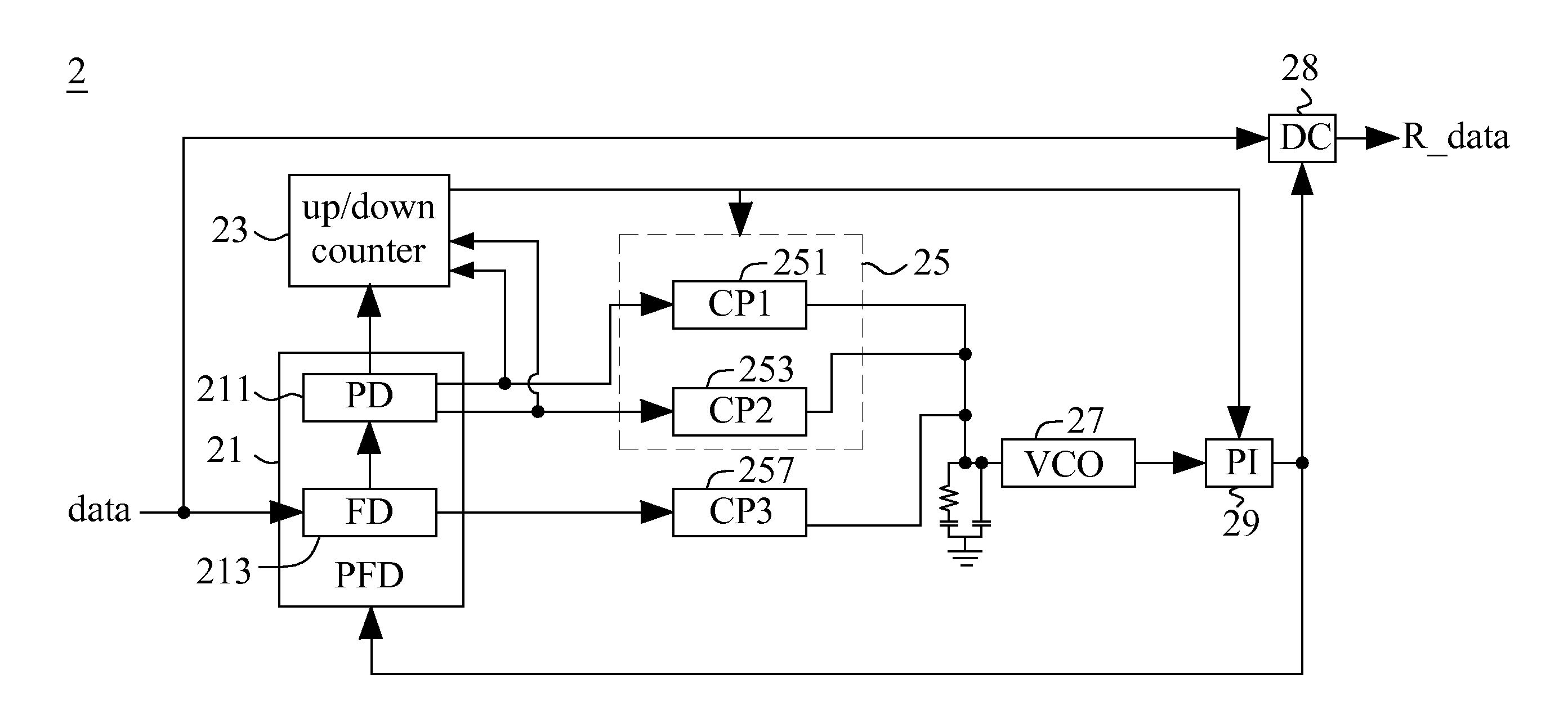
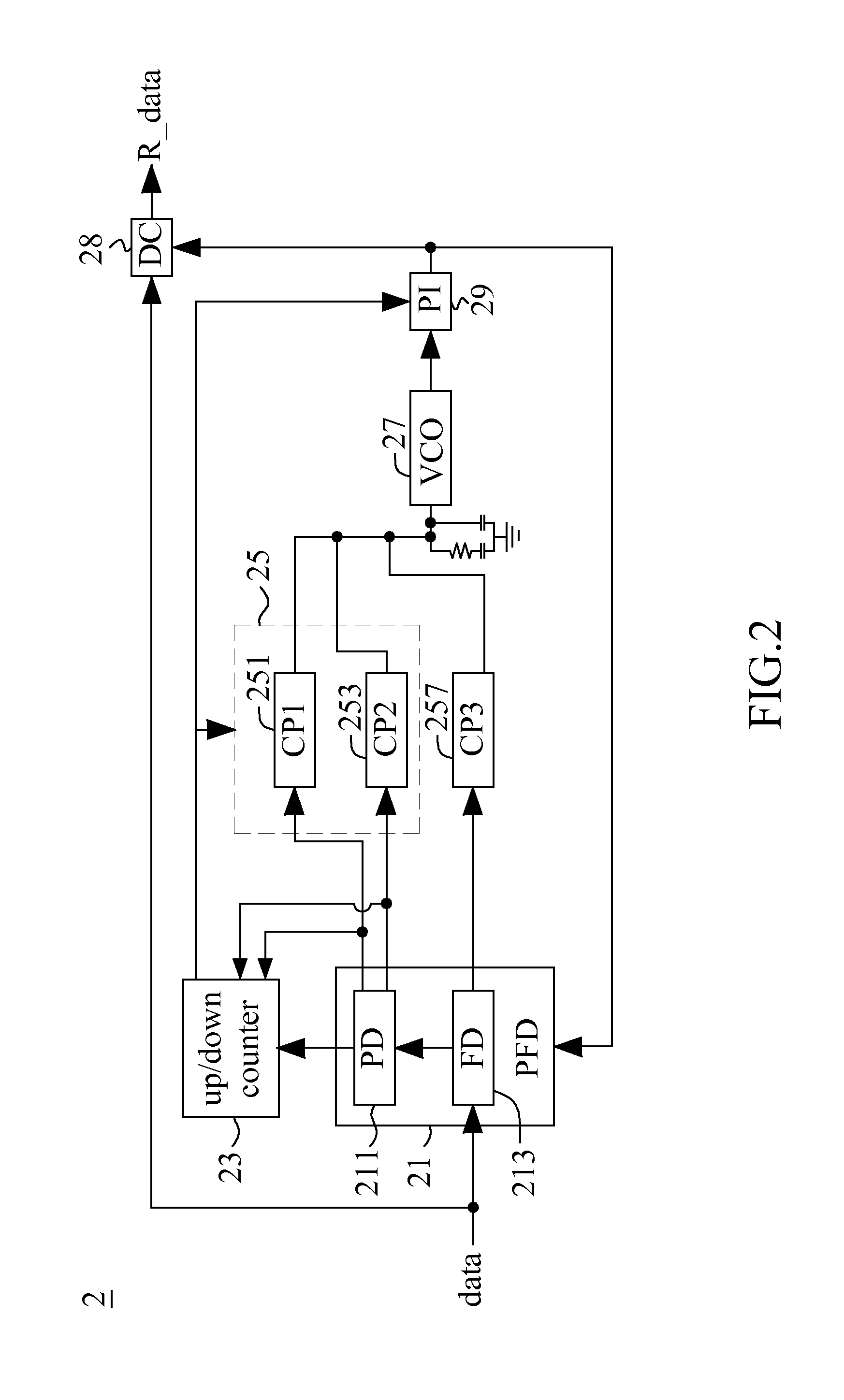
[0022]Firstly, FIG. 2 illustrates a clock and data recovery (CDR) architecture 2 according to one embodiment of the present invention. As shown in FIG. 2, the CDR architecture 2 includes a phase / frequency detector (PFD) 21 which consists of a frequency detector 213 and a phase detector 211. In one embodiment, the frequency detector 213 comprises a ¼ rate digital quadricorrelator frequency detector (DQFD) which can be implemented by referencing the prior art (i.e., “A 3.125-Gb / s Clock and Data Recovery Circuit for the 10-Gbase-LX4 Ethernet,”IEEE Journal of Solid-State Circuits, vol. 39, no. 8, pp. 1723-1732, proposed by Yang et al. in August 2004). The discussion of the detailed operation of the frequency detector 213, described below, is thus omitted here for brevity.
[0023]Referring to FIG. 3, the frequency detector 213 utilizes 8 D-FFs to respectively sample a received data signal based on a plurality of clock signals with different phases, and then uses plural XOR gates and OR gat...
PUM
 Abstract
Description
Claims
Application Information
 - R&D
- Intellectual Property
- Life Sciences
- Materials
- Tech Scout
- Unparalleled Data Quality
- Higher Quality Content
- 60% Fewer Hallucinations
Browse by: Latest US Patents, China's latest patents, Technical Efficacy Thesaurus, Application Domain, Technology Topic, Popular Technical Reports.
© 2025 PatSnap. All rights reserved.Legal|Privacy policy|Modern Slavery Act Transparency Statement|Sitemap|About US| Contact US: help@patsnap.com


