
Cordless magnetic drill

a magnetic drill and cordless technology, applied in the field of magnetic drills, can solve the problems of inconvenient magnetic drills, hazardous complex power supply lines of magnetic drills, and inability to guarantee the safety of magnetic drills in a complex working environment, so as to improve the convenience of use, fill the gap in the market, and improve the effect of use safety

Inactive Publication Date: 2013-05-02
WOELDERS NIELS J
View PDF21 Cites 26 Cited by
  • Summary
  • Abstract
  • Description
  • Claims
  • Application Information

AI Technical Summary

Benefits of technology

The present invention is a cordless magnetic drill that uses a portable cordless power source, eliminating the need for external power sources, electric wires, or air hoses. This improvement overcomes various defects of existing corded magnetic drills and fills the gap in the market. The cordless drill is no longer limited by the external power source, improving safety and convenience. It can be used for drilling work of various high difficulties at any operating location without being influenced by the operating environment, improving work efficiency and simplifying the working procedure. However, if the power source fails, the magnetic base will lose magnetic field and the drill may slip off and even fall from the working surface, causing danger. To address this issue, the present invention further improves the design of the magnetic base to guarantee that the drill can be reliably and firmly held on the surface, improving operational safety.

Problems solved by technology

Therefore, in the working environment of the magnetic drills extra space has to be provided for installing the external power sources, and electric wires or air hoses have to be set up between the working positions of the magnetic drills and the external power sources, as a result the safety of the magnetic drills cannot be guaranteed in a complex working environment.
For example, when the magnetic drills are operated high above the ground, relatively longer electric wires or air hoses are needed because the external power sources cannot be easily reached at high heights, because of this the magnetic drills are inconvenient to use and are potentially dangerous whilst operation, furthermore when the magnetic drills are operated in a humid environment, the complex power supply lines of the magnetic drills can be hazardous whilst using the magnetic drills.
Therefore, existing corded magnetic drills not only have great limitations, but are also not entirely safe.

Method used


Image

  • Cordless magnetic drill
  • Cordless magnetic drill
  • Cordless magnetic drill

Examples


embodiment 1

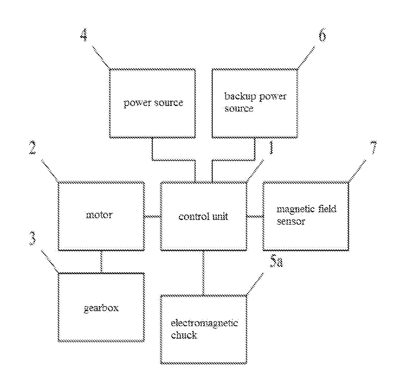
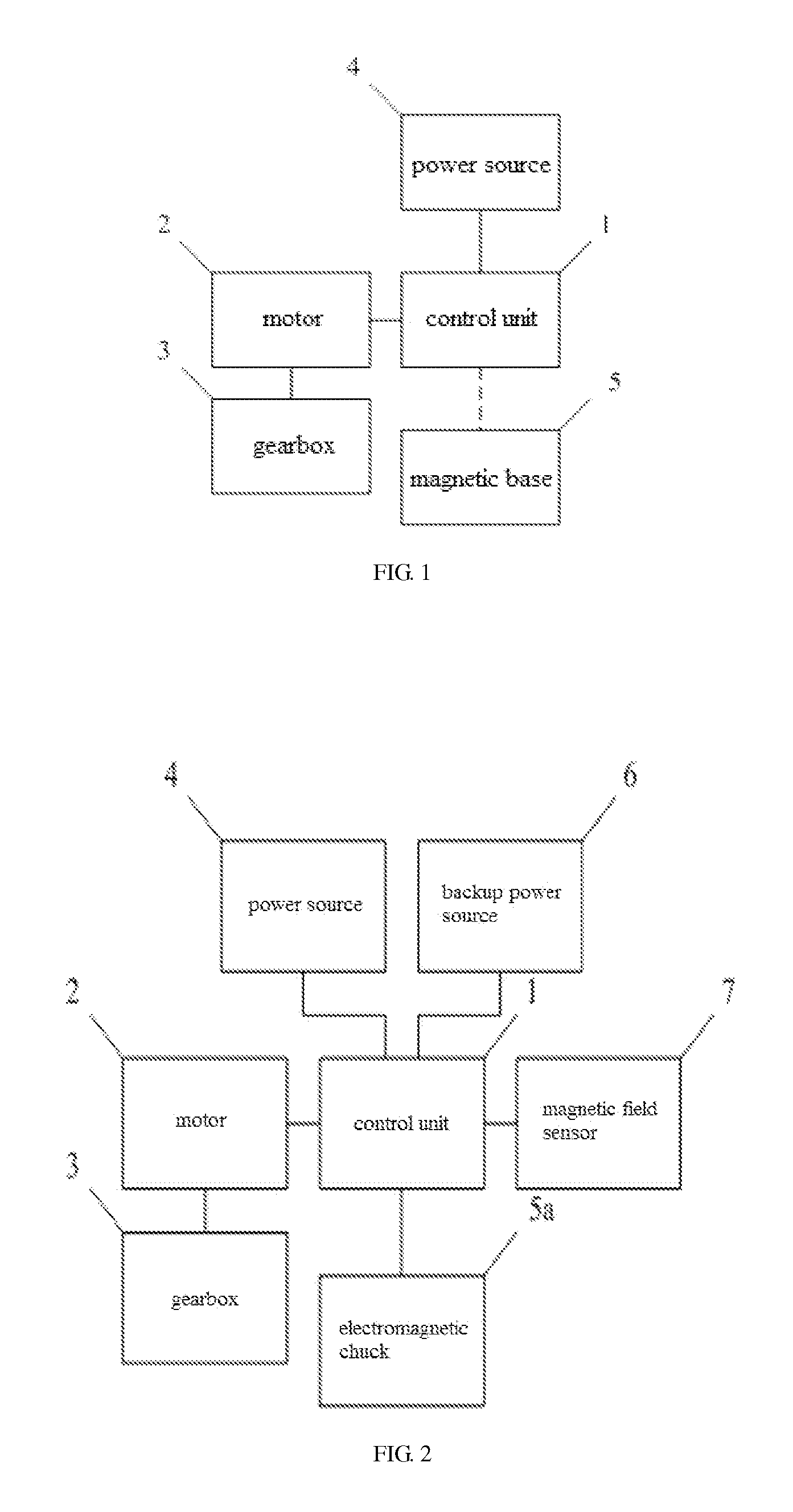
[0040]As shown in FIG. 2, in the embodiment, the magnetic base 5 adopts an electromagnetic chuck 5a and the power source 4 supplies power to the electromagnetic chuck 5a for generating the magnetic field. The control unit 1 respectively establishes and cuts off the connection between the power source 4 and the electromagnetic chuck 5a to generate or eliminate the magnetic field of the electromagnetic chuck 5a when the cordless magnetic drill starts working and finishes working, and the power source 4 constantly keeps the connection with the electromagnetic chuck 5a to guarantee that the cordless magnetic drill is reliably held on the working surface when the cordless magnetic drill is working.

[0041]When the energy of the power source 4 is nearly exhausted, in order to prevent the cordless magnetic drill from slipping off and even falling off from the working surface cased by the loss of the holding force as the electromagnetic chuck 5a suddenly powers off, the control unit 1 can pre...

embodiment 2

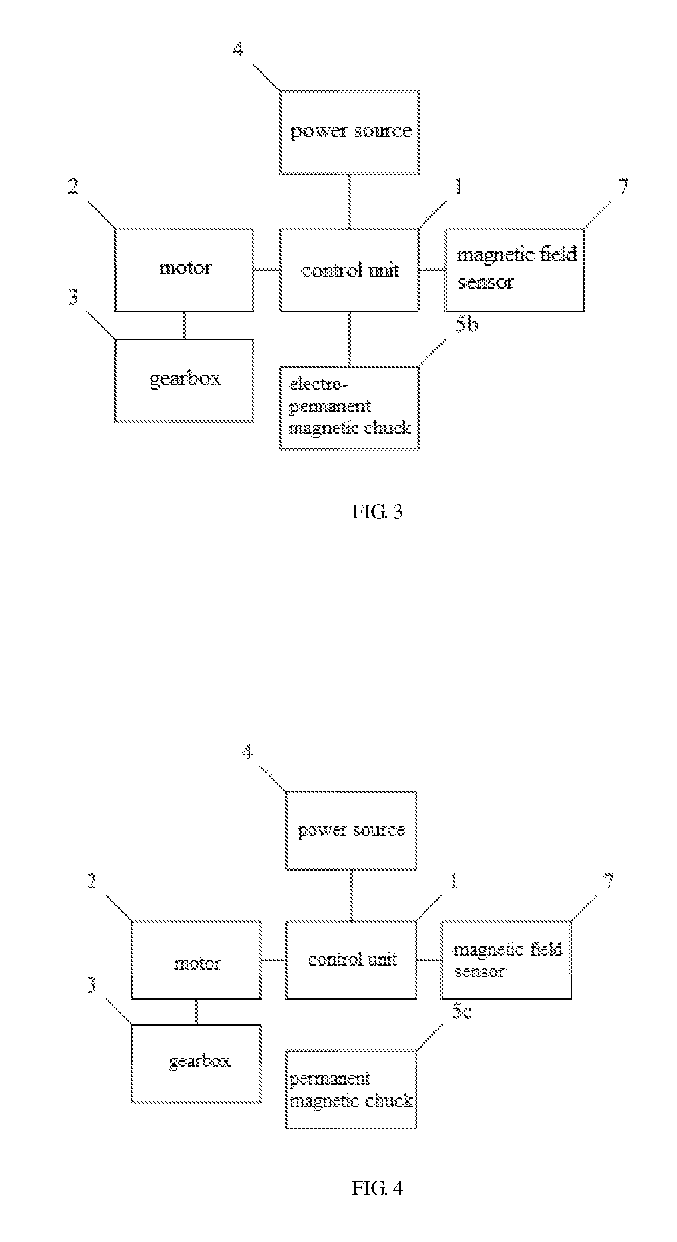
[0048]The structure of the cordless magnetic drill in this embodiment is very similar to that in the embodiment 1, and therefore the only difference will be detailed in the following. As shown in FIG. 3, in this embodiment, the magnetic base 5 adopts an electro-permanent magnetic chuck 5b, which does not need to be powered by the power source 4 in normal operation, but only needs an electric turning-on / off signal transmitted from the control unit 1 when the electro-permanent magnetic chuck 5b is turned on and off, for example, the operator can input an instruction for turning on / off the electro-permanent magnetic chuck 5b to the control unit 1 through the man-machine interaction interface, the control unit 1 will then according to the received instruction turn the magnetic field of the electro-permanent magnetic chuck 5b on or off.

[0049]As the electro-permanent magnetic chuck 5b can permanently generate the magnetic field without any power, in this embodiment the normal holding forc...

embodiment 3

[0051]The structure of the cordless magnetic drill in this embodiment is very similar to that in embodiment 2, and therefore the only difference will be detailed in the following. As shown in FIG. 4, in this embodiment, the magnetic base 5 adopts a permanent magnetic chuck 5c, which can spontaneously and continuously generate a magnetic field to reliably hold the cordless magnetic drill on the working surface with no need to be powered by the power source 4 or controlled by the control unit 1. When the cordless magnetic drill starts or stops working, sticking the permanent magnetic chuck 5c on the working surface or releasing the permanent magnetic chuck 5c from the working surface can be realized by a simple mechanical structure directly installed on the permanent magnetic chuck 5c, which is well known in the industry, and therefore is not repeatedly detailed herein, or the mechanical control backstage for performing the sticking and the releasing can also be integrated on the man-...


PUM

PropertyMeasurementUnit
speedaaaaaaaaaa
poweraaaaaaaaaa
voltageaaaaaaaaaa

Abstract

A cordless magnetic drill is disclosed. The drill comprises a control unit, a motor which is connected with the control unit, a gearbox which is connected with the motor, a power source which is connected with the control unit, and a magnetic base. The gear box is used for regulating the output rotation speed of the motor. The power source is used for supplying power to the motor. The magnetic base can be an electromagnetic chuck, an electro-permanent magnetic chuck, a permanent magnetic chuck or the combination of a permanent magnetic chuck and an electromagnetic chuck. The control unit is used for controlling the operations of the motor and the power source and establishing or cutting off the connection between the power source and the motor. The cordless magnetic drill of the present invention is convenient and very safe to use.

Description

FIELD OF THE INVENTION[0001]The invention relates to a magnetic drill, in particular to a cordless magnetic drill.BACKGROUND OF THE INVENTION[0002]Magnetic drills have been widely used in various fields such as steel structure processing, shipbuilding, bridge engineering, petroleum engineering, power station maintenance and railway construction etc. So far, all magnetic drills on the market have cords, i.e. the magnetic drills have to be connected with external power sources by electric wires or have to be connected with air pumps by air hoses when in use to obtain the power required for running. Therefore, in the working environment of the magnetic drills extra space has to be provided for installing the external power sources, and electric wires or air hoses have to be set up between the working positions of the magnetic drills and the external power sources, as a result the safety of the magnetic drills cannot be guaranteed in a complex working environment. For example, when the ...

Claims


Application Information

Patent Timeline
Patent Type & Authority Applications(United States)
IPC IPC(8): B23B45/02B23Q15/007
CPCB23B45/00B25H1/0071B23B45/02Y10T408/21Y10T408/14Y10T408/655B23Q15/007
Inventor WOELDERS, NIELS J.
Owner WOELDERS NIELS J
Learn More