
Exhaust gas purification system for internal combustion engine

a technology of exhaust gas purification system and internal combustion engine, which is applied in the direction of exhaust treatment electric control, electrical control, separation process, etc., can solve the problems of loss of controllability, achieve improved prevent thermal degradation of catalyst held in dpf, and improve controllability of dpf inlet temperature

Active Publication Date: 2013-05-02
MITSUBISHI HEAVY IND ENGINE & TURBOCHARGER LTD
View PDF1 Cites 3 Cited by
  • Summary
  • Abstract
  • Description
  • Claims
  • Application Information

AI Technical Summary

Benefits of technology

This invention provides an integrator resetter that prevents the temperature of an exhaust gas sensor from being affected by sudden changes in the flow rate. This prevents a decrease in the temperature during a sudden drop in exhaust gas flow rate, which can cause issues with the regeneration of a diesel particulate filter. By using this invention, the target temperature of the exhaust gas can be set higher, reducing the time required for regeneration and avoiding oil dilution.

Problems solved by technology

In an operating condition in which the flow rate of the exhaust gas has decreased suddenly and remains low for a while, in the conventional technique, when there was (accumulated) still an integral value before the sudden drop of the exhaust gas flow rate in the integrator of the feedback controller, the response of the DPF inlet temperature was slow (deadtime was long) particularly when the flow rate was decreasing, so that it would take time to output accumulated integral value, during which the integral values are added as correcting variables, whereby the DPF inlet temperature was raised, resulting in a loss of the controllability.

Method used


Image

  • Exhaust gas purification system for internal combustion engine
  • Exhaust gas purification system for internal combustion engine
  • Exhaust gas purification system for internal combustion engine

Examples


first embodiment

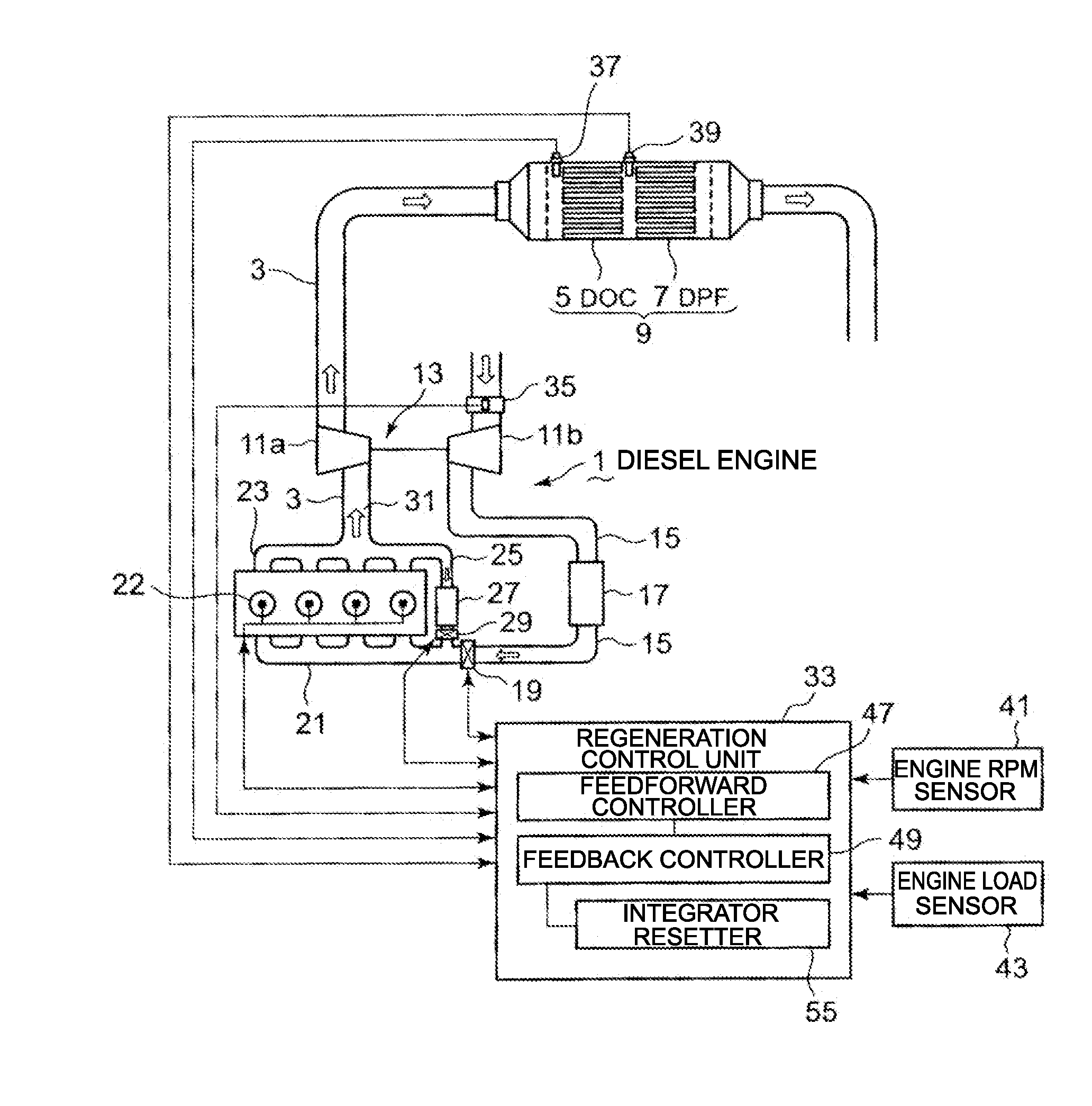
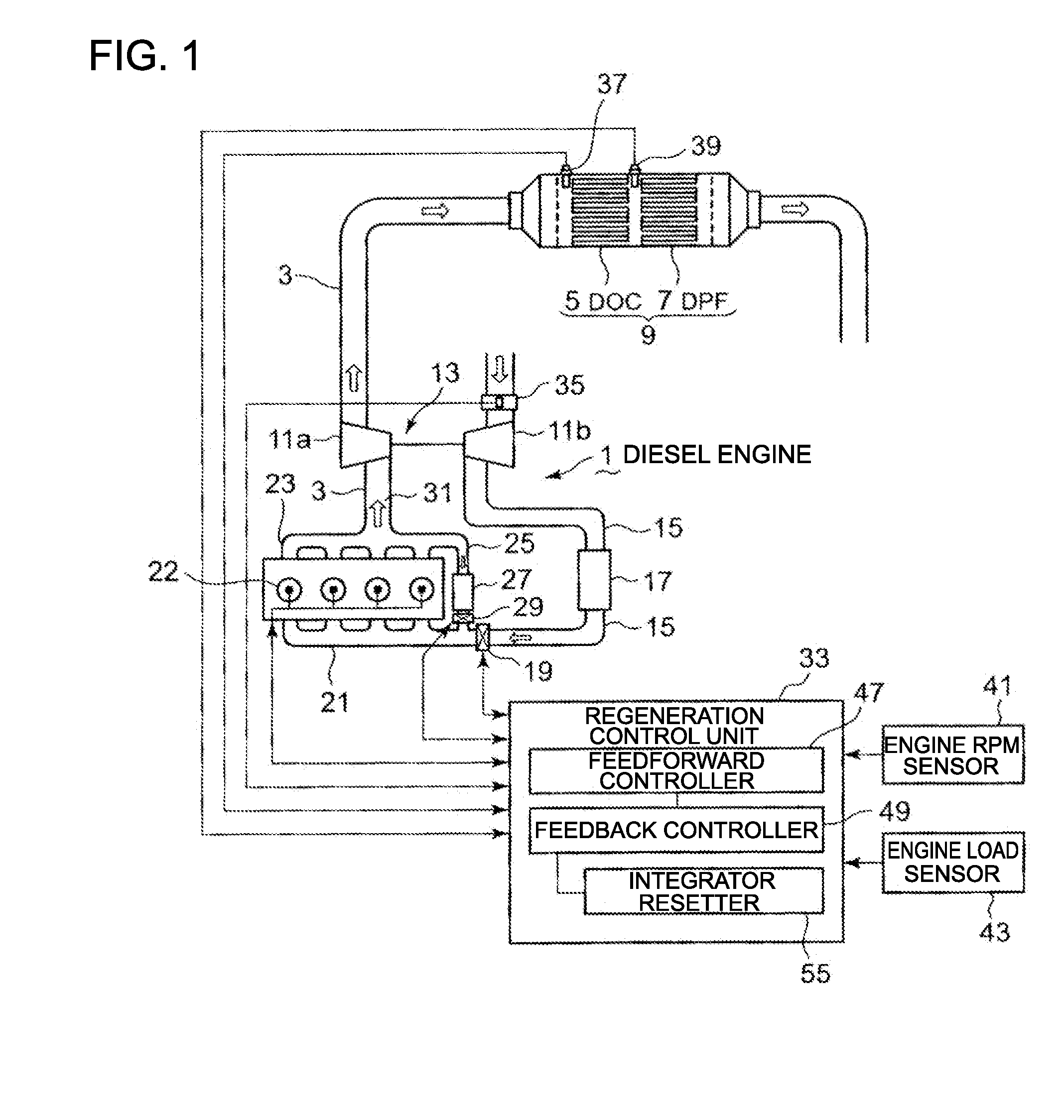
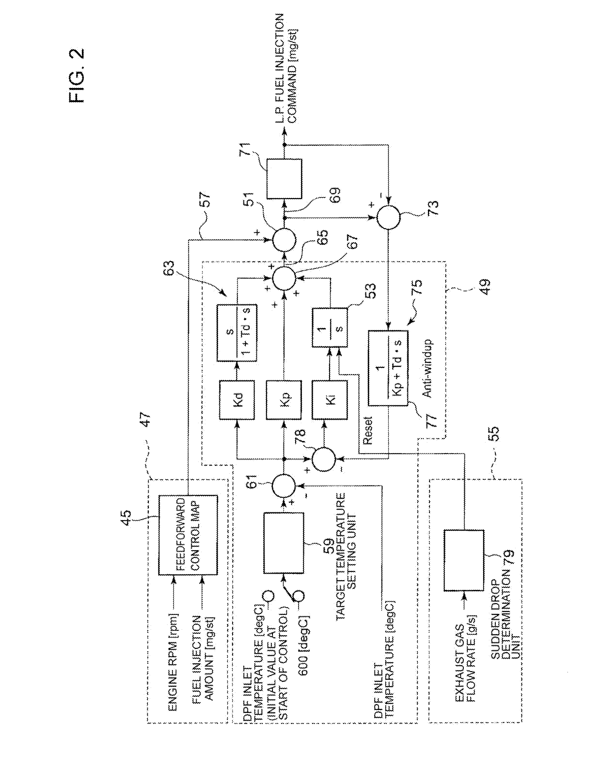
[0070]Next, a first embodiment of the control of the amount of late post-injection by the regeneration control unit 33 will be described with reference to the control configuration block diagram of FIG. 2,

[0071]The regeneration control unit 33 controls the amount of the late post-injection (manipulated variable) to constantly keep the inlet temperature of the DPF 7 at the setpoint of about 600° C. and for that purpose includes: A feedforward controller 47 that outputs a command indicative of a basic injection amount (basic variable) of late post-injection based on a feedforward control map 45 that defines basic injection amounts preset in accordance with the engine rpms and fuel injection amounts (engine loads); a feedback controller 49 that outputs a command indicative of a correction amount of late post-injection (correcting variable) for achieving the target temperature of the DPF 7; and an injection amount (manipulated variable) adding unit 51 (see FIG. 2) that computes an amoun...

second embodiment

[0095]Next, a second embodiment of the control of the amount of late post-injection by the regeneration control unit 33 will be described with reference to the control configuration block diagram of FIG. 3.

[0096]The feedforward controller 47 is the same as that of the first embodiment and therefore will not be described again. The integrator resetter 55 of the first embodiment is not provided here. The second embodiment is characteristic in that it has a different feedforward controller than that (47) of the first embodiment.

[0097]As shown in FIG. 3, unlike the first embodiment, the feedforward controller 81 of the second embodiment does not output a command indicative of a basic injection amount (basic variable) of late post-injection based on a map that defines feedforward commands determined through tests and preset beforehand in accordance with various operating conditions. Instead, the feedforward controller outputs a command indicative of a basic injection amount that it calcu...


PUM


Abstract

An exhaust gas purification system includes a feedforward controller 47, a feedback controller 49 outputting a correcting variable for achieving a target temperature of DPF 7, and a variable adding unit 51 that adds the correcting variable output from the feedback controller 49 to a basic variable output from the feedforward controller 47 to compute a manipulated variable. The system further includes either one of an integrator resetter 55 that resets the integral value of an integrator that forms the feedback controller 49 when the amount of exhaust gas has suddenly dropped, and a basic variable calculating unit that calculates the basic variable to be output from the feedforward controller based on a signal representing the flow rate of exhaust gas.

Description

TECHNICAL FIELD[0001]The present invention relates to a diesel engine exhaust gas purification system, and more particularly to the control of temperature at the inlet of a diesel particulate filter (hereinafter, DPF) that collects particulate matter (hereinafter, PM) contained in the exhaust gas, during regeneration of the DPF.BACKGROUND ART[0002]PM reduction is as important as NOX reduction in exhaust gas regulations of diesel engines, DPF is known as an effective technique in this regard.[0003]DPF is a PM collecting device that uses a filter. As the PM continues to accumulate in the DPF in engine operating conditions with low exhaust gas temperatures, forced regeneration is carried out wherein the temperature is forcibly raised to burn the PM.[0004]Common means of raising the temperature include delaying the fuel injection timing, post-injection, and intake throttling, which all encompass the problem of adversely affecting the fuel economy. On the other hand, higher temperatures ...

Claims


Application Information

Patent Timeline
Patent Type & Authority Applications(United States)
IPC IPC(8): B01D53/94
CPCF01N3/106F01N13/0097F01N2900/0408F01N2900/0418F01N2900/1602F02B37/00F02D41/029F02D41/1445F02D2041/1409F02D2041/141F02D2200/0802Y02T10/47B01D53/9495F02D2041/1422F01N9/002Y02T10/40
Inventor IDE, KAZUNARIIKAWA, YOSHIKATSU
Owner MITSUBISHI HEAVY IND ENGINE & TURBOCHARGER LTD
Learn More