Signal transmission system, connector apparatus, electronic device, and signal transmission method

a technology of connectors and transmission systems, applied in the direction of coupling device connections, near-field systems using receivers, high-frequency circuit adaptations, etc., can solve the problems of increasing the number of input/output terminals, limiting the transmission speed and transmission capacity, and difficult to manufacture connectors using signal shaping techniques. , to achieve the effect of high speed, large capacity and high speed

Active Publication Date: 2013-05-02
SONY SEMICON SOLUTIONS CORP
View PDF14 Cites 295 Cited by
  • Summary
  • Abstract
  • Description
  • Claims
  • Application Information

AI Technical Summary

Benefits of technology

[0015]According to the present invention, connection interfaces of signals for which high speed and large capacity are required can be realized, different from connection interfaces using contacts.
[0016]The present invention can be applied to a connector not having a structural room in which contact pins cannot be additionally provided. The connection interfaces using the contacts can be continuously maintained. In this case, connection interfaces of signals for which high speed and large capacity are required can be realized while backward compatibility with an existing connector is maintained.

Problems solved by technology

1) In signal transmission using the electrical contact, there are limitations in a transmission speed and a transmission capacity. This is because shapes and placements of connector electrodes designed for old generations are not suitable for a broadband. In order to overcome the limitations, a method using signal shaping techniques such as a cable equalizer, an echo canceller, and a crosstalk canceller is considered. However, if a wider bandwidth is required (for example, more than 5 Gb / s), it is very difficult to manufacture the connector using the signal shaping techniques.
2) A method of increasing the number of wiring lines and decreasing a transmission speed per signal line by parallelization of signals is considered to cope with a problem of high-speed data transmission. However, if the method is used, this may increase the number of input / output terminals, which results in deteriorating compatibility with the existing connector.
3) A method of adding a new signal interface for high-speed transmission from USB 2.0 to USB 3.0, separately from the existing signal interface, is also known. However, it is difficult for the method to be applied to the case of a shape of a connector in which it is difficult to add pins under constraints where the pins can be inserted into a connector of a current generation.

Method used


Image

  • Signal transmission system, connector apparatus, electronic device, and signal transmission method
  • Signal transmission system, connector apparatus, electronic device, and signal transmission method
  • Signal transmission system, connector apparatus, electronic device, and signal transmission method

Examples


second embodiment (

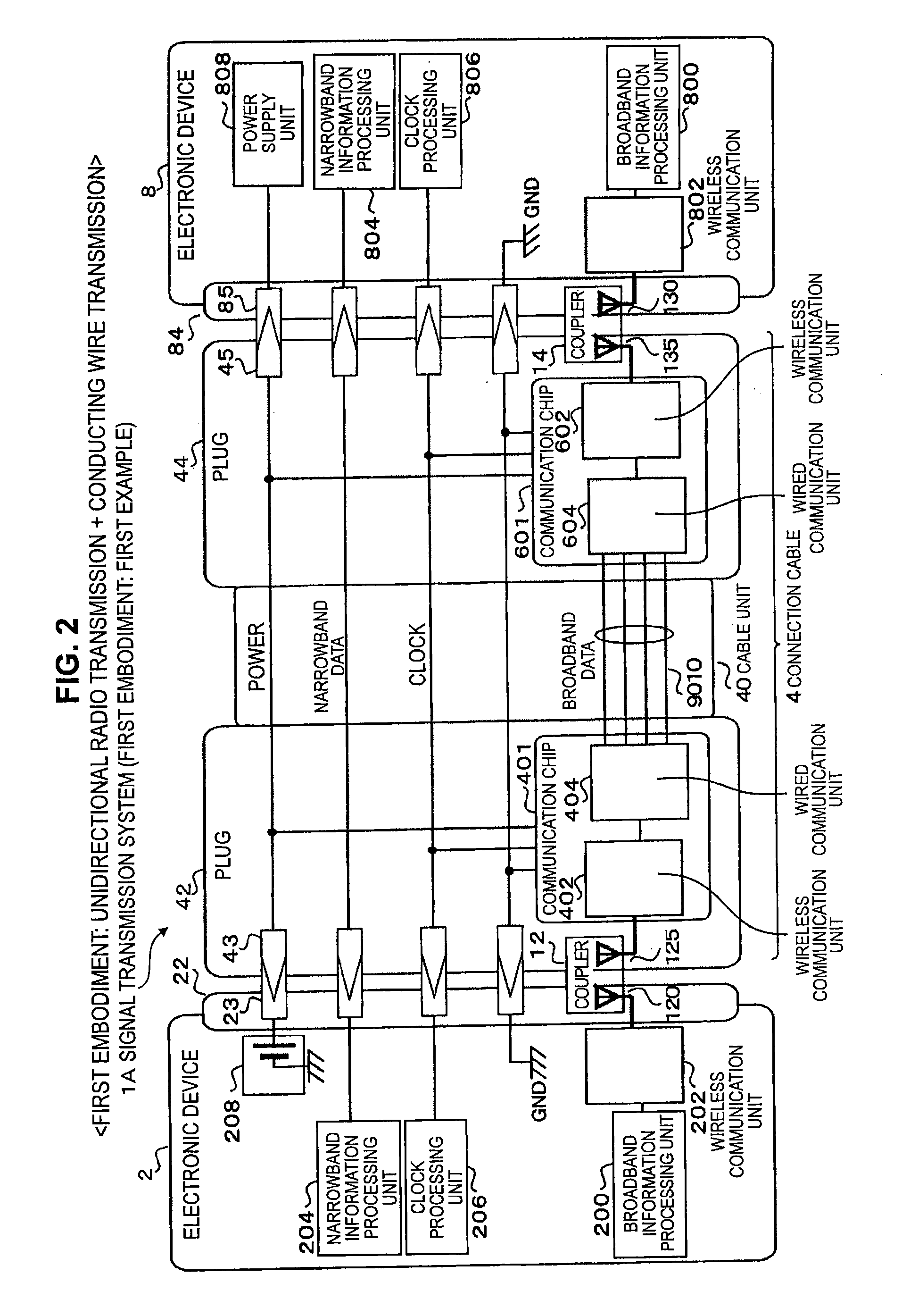
3. Second Embodiment (Bidirectional Signal Transmission: Transmission using Conducting Wire in Cable)

third embodiment (

4. Third Embodiment (Connection Compatibility Detection Mechanism)

fourth embodiment (

5. Fourth Embodiment (Optical Transmission in Cable)

[0049]6. Fifth Embodiment (Application with respect to Power Supply Cable)

7. Comparison with Examples

[Basic Concept]

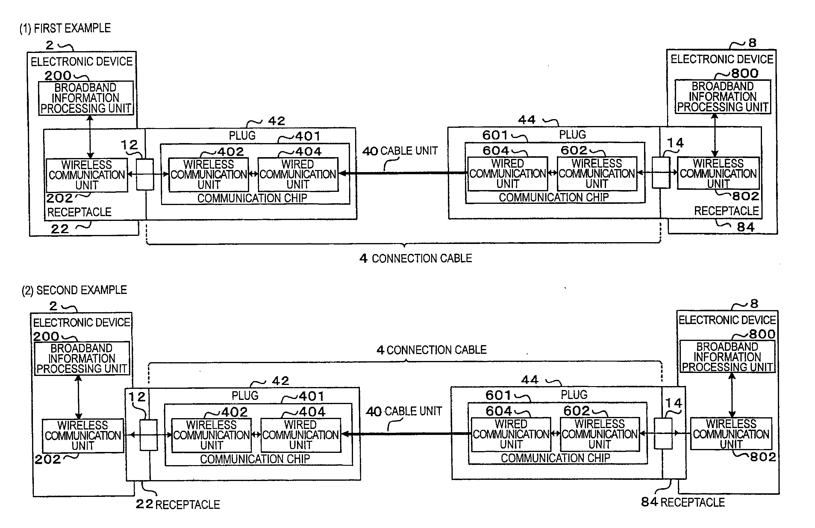
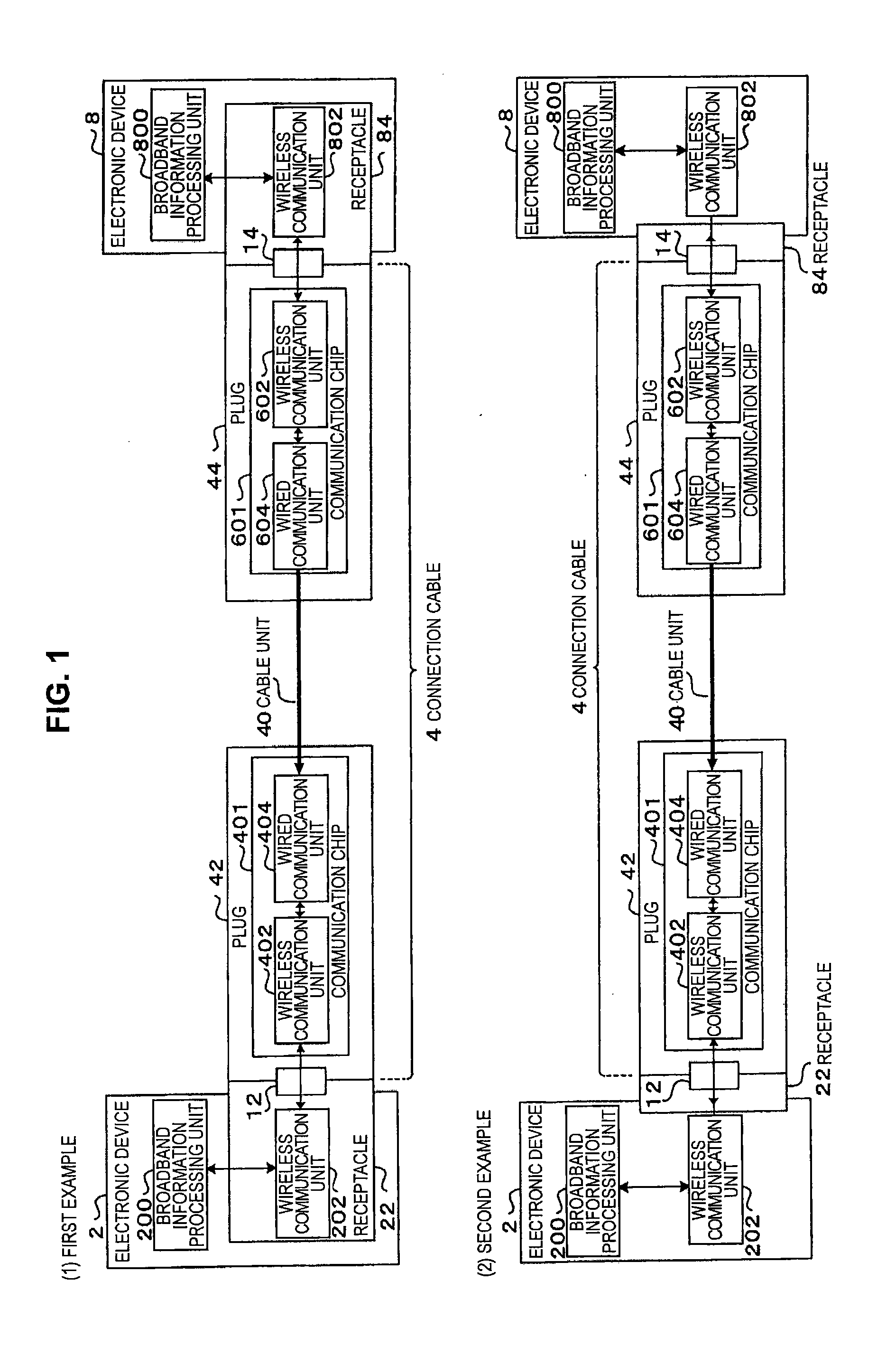
[0050]A structure according to this embodiment is characterized in that, when a first electronic device and a second electronic device are connected by a cable, a signal transmission in a connector portion is performed using radio transmission, not an electrical contact based on a contact (pin). When the electronic device and the cable are connected (fitted) by a connector (that is, in a state in which both the electronic device and the cable are arranged at a relatively short distance), a transmission object signal is converted into a radio signal, which is then transmitted through a radio signal transmission path. As a mechanism for achieving the configuration described above, a coupling unit that is connected to a signal converting unit (hereinafter, also called a wireless communication unit) to execute modulation ...


PUM


Abstract

A signal transmission system including: a first connector apparatus, and a second connector apparatus that is coupled with the first connector apparatus. The first connector apparatus and the second connector apparatus are coupled together to form an electromagnetic field coupling unit, and a transmission object signal is converted into a radio signal, which is then transmitted through the electromagnetic field coupling unit, between the first connector apparatus and the second connector apparatus.

Description

TECHNICAL FIELD[0001]The present invention relates to a signal transmission system, a connector apparatus, an electronic device, and a signal transmission method.BACKGROUND ART[0002]When a signal is transmitted from one device to the other device, signal transmission (including power supply) may be performed through a connector.[0003]In this case, when electrical connection is performed through the connector, there are standards in a casing shape and a signal interface including a terminal unit and a fitting structure and electrical and mechanical interfaces of one device and the other device are defined according to the standards.[0004]For example, recently, downsizing of electronic devices such as a mobile phone, a PDA, a video camera, and a digital camera has progressed and new interfaces that enable high-speed transmission have been standardized. In addition, a shape of a small connector has been standardized to correspond to the downsizing of devices such as a mini-USB and an H...

Claims


Application Information

Patent Timeline
Patent Type & Authority Applications(United States)
IPC IPC(8): H04B7/24H01P5/107H04B1/40H04B3/02H04B5/02
CPCH04B7/24H05K2201/09754H01P5/107H04B3/56H01R2103/00H01R13/6461H01R13/665H01R24/28H01R24/76H05K1/0225H05K1/0239H05K2201/093H05K2201/09672H05K2201/0969H01P3/121H01P1/208H01P3/165H01P5/024H01P5/082H01P5/087H01P5/1022H01P5/18H01P5/182H01P5/188H04L12/00H01P3/12H01P5/02
Inventor KIKUCHI, HIDEKAZUMOGI, TAKAYUKIAKIYAMA, YOSHIYUKIKAWAMURA, HIROFUMI
Owner SONY SEMICON SOLUTIONS CORP
Why Eureka
Try Eureka