
Retina prosthesis

a retinal prosthesis and prosthesis technology, applied in the field of retinal prosthesis, can solve the problems of not being able to the device performance is still limited, and the current technology cannot achieve the resolution of the normal retina, so as to maximize the likelihood, maximize the likelihood, and avoid local maxima

Active Publication Date: 2013-05-02
CORNELL UNIVERSITY
View PDF6 Cites 19 Cited by
  • Summary
  • Abstract
  • Description
  • Claims
  • Application Information

AI Technical Summary

Benefits of technology

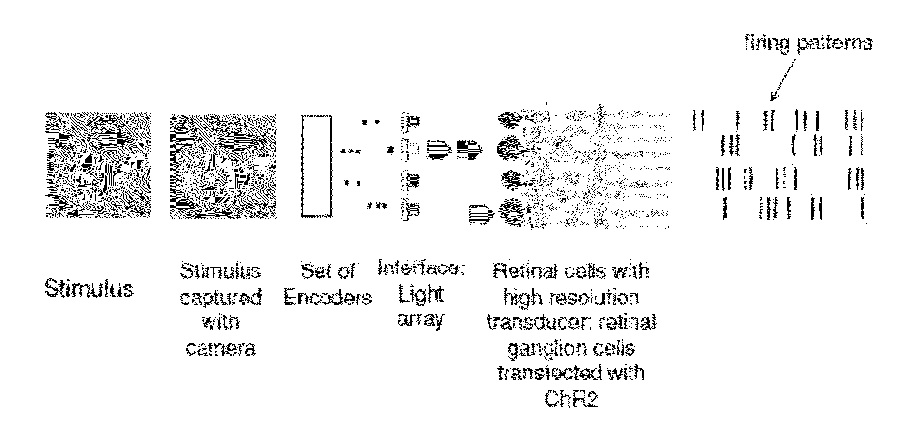
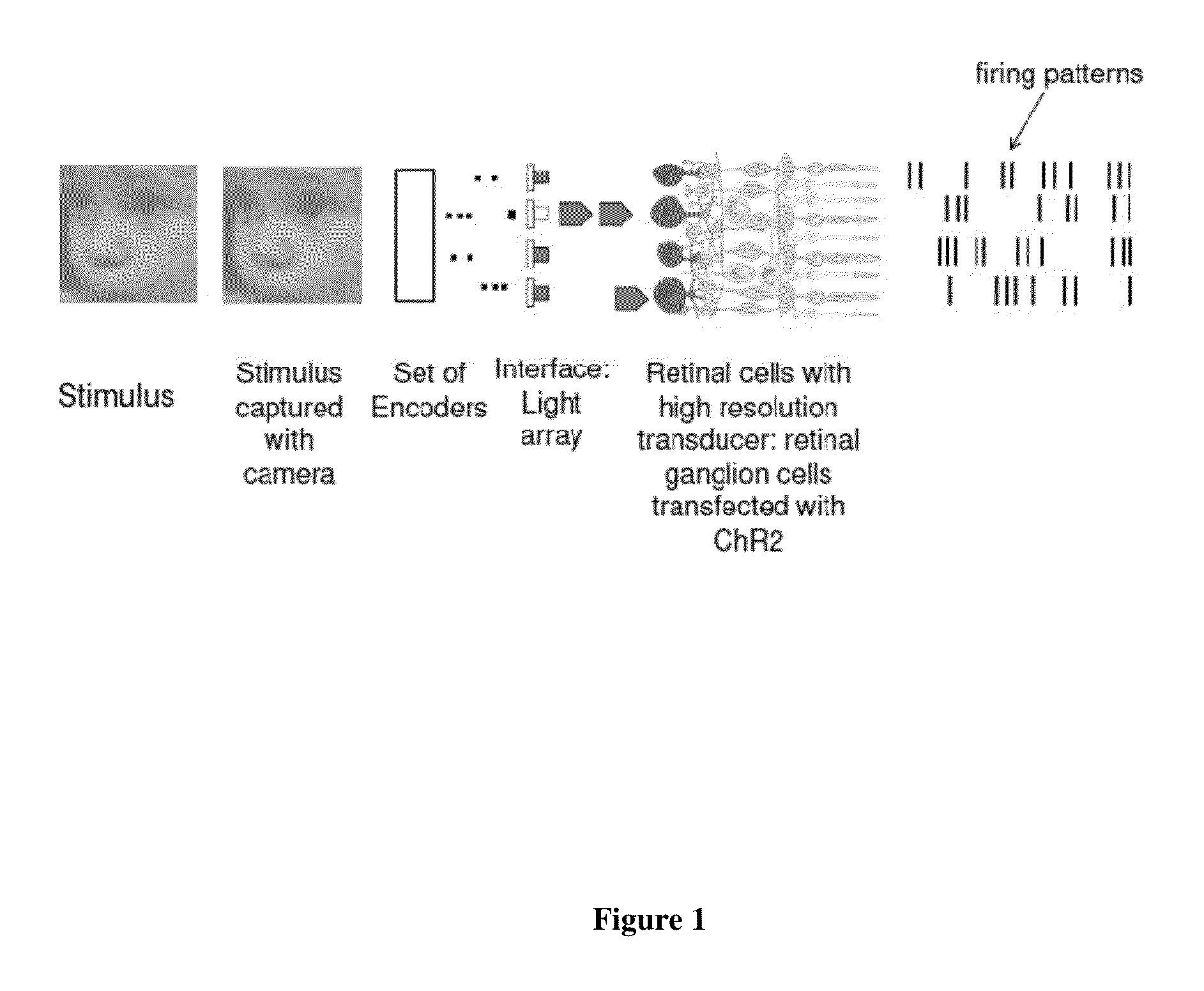
The patent describes a method for restoring or improving vision by using a stimulus that is transformed into a set of codes, which are then activated to generate retinal cell responses. The method is characterized by an input / output transformation that mimics the input / output transformation of a retinal cell. The encoded data can be used to restore or improve vision by applying a spatiotemporal transformation to the data and then activating a plurality of retinal cells with a high resolution transducer. The performance of the method is measured by the fraction correct on a forced choice visual discrimination task and the correlation coefficient between the test stimulus and the stimulus reconstructed from the codes. The method can be implemented using a computer-readable medium and a processor.

Problems solved by technology

While the patients can see some light, the performance of the devices is still quite limited: patients are, for example, able to see spots and edges (Nanduri et al., 2008; Chader et al., 2009), which provide some ability for navigation and gross feature detection, but nothing close to normal vision has been possible.
While there have been some increases in resolution, the current technology does not achieve the resolution of the normal retina, as it is not yet practical to stimulate individual cells with electrodes, and the technical challenge is severe: finer electrodes require more current, which leads to tissue burning (see, for example, the title and agenda for a recent conference on retinal prosthetics: “The Eye and The Chip 2010: 2010 Special Emphasis on Retinal Stimulation Safety for Neuro-Prosthetic Devices”).
Current optogenetic approaches are similarly limited.

Method used


Image

  • Retina prosthesis
  • Retina prosthesis
  • Retina prosthesis

Examples


example 1

Method of Building the Encoders

Constructing the Encoders Using an Linear-Nonlinear-Poisson (LNP) Cascade

[0226]The parameters for the encoders were constructed from the responses to two sets of stimuli: binary spatio-temporal white noise (WN) and a grayscale natural scene movie (NS) recorded in New York City's Central Park. Both stimuli were presented at a frame rate of 15 Hz, and had the same mean luminance (0.24 μW / cm2 on the retina) and contrast (root-mean-squared (RMS) contrast was 0.087 μW / cm2). For the preprocessing step, we chose a=0, and b=255 / 0.48 μW / cm2, so that the visual stimuli are mapped into the numerical range 0-255 (as described above in section entitled, “Encoders”.

[0227]To determine the spatiotemporal transformation, we used a linear-nonlinear model as described above in the same section (see also, Victor and Shapley 1979; Paninski et al. 2007; Pillow et al. 2008; Nirenberg et al. 2010). Parameters for the model were determined by maximizing the likelihood that the...

example 2

Determining the Parameters for the Spatiotemporal Transformation

[0235]We describe a procedure to determine the parameters for the spatiotemporal transformations. Parameters discussed are as in the section “Encoders” above.

[0236]In this example, first, the experiment is performed, and ganglion cell responses to WN and NS stimuli are collected (see “Example 1—Method of Building the Encoders” for an example of stimuli). Next, the reverse correlation between the ganglion cell action potential times and the stimulus intensity is calculated, to determine a starting set of values for the linear filter Lm. Next, the linear filter is assumed to be separable, a product of a spatial function and a temporal function. The spatial function is parameterized as a 10 by 10 grid of weights, and the temporal function is parameterized as the sum of 10 weighted temporal basis functions. At this stage, the nonlinearity Nm is assumed to be an exponential function to ensure there are no local maxima. Next,...

example 3

Comparison of Amount of Information Carried by Virtual Retinal Cell and Real Retinal Cell

[0237]To build the data set, we recorded the responses of several hundred mouse retinal ganglion cells (515 cells) to a broad range of stimuli, including natural and artificial stimuli, which for this experiment was checkerboard, natural scenes, and drifting gratings. For each cell, we constructed its encoder (also referred to as its virtual retinal cell, or model cell). This was achieved as follows. We presented WN (white noise) and NS (natural or naturalistic stimuli) stimuli to retinas and recorded the responses of the ganglion cells and parameterized the stimulus / response relationship for each cell, as described above. We then tested the encoders using additional natural scene and drifting grating responses. Thus, all tests were performed using novel stimuli.

[0238]FIG. 3 shows the results of the information analysis. We recorded from several hundred ganglion cells and modeled their responses...


PUM


Abstract

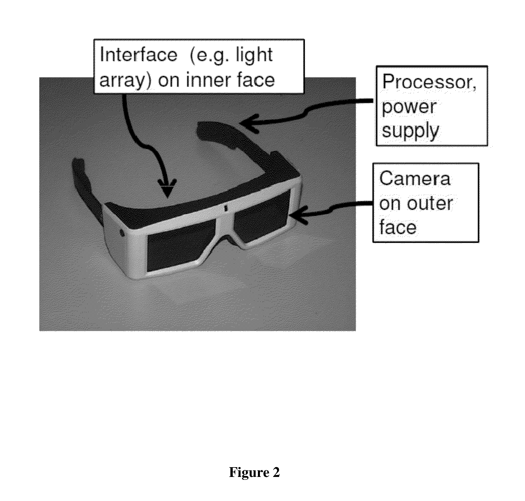
The invention provides a retinal prosthetic method and device that mimics the responses of the retina to a broad range of stimuli, including natural stimuli. Ganglion cell firing patterns are generated in response to a stimulus using a set of encoders, interfaces, and transducers, where each transducer targets a single cell or a small number of cells. The conversion occurs on the same time scale as that carried out by the normal retina. In addition, aspects of the invention may be used with robotic or other mechanical devices, where processing of visual information is required. The encoders may be adjusted over time with aging or the progression of a disease.

Description

CROSS REFERENCE TO RELATED APPLICATION[0001]This application is a continuation-in-part of International Patent Application No. PCT / US2011 / 026526 (filed on Feb. 28, 2011) which in turn claims the benefit under 35 U.S.C. §119(e) of U.S. Provisional Application Nos. 61 / 308,681 (filed on Feb. 26, 2010), 61 / 359,188 (filed on Jun. 28, 2010), 61 / 378,793 (filed on Aug. 31, 2010), and 61 / 382,280 (filed on Sep. 13, 2010).STATEMENT REGARDING FEDERALLY SPONSORED RESEARCH OR DEVELOPMENT[0002]This invention was made with U.S. Government support under GM0779 awarded by the National Institute of Health (NIH), and under FEY019454A awarded by the National Eye Institute. The U.S. Government has certain rights in the invention.FIELD OF THE INVENTION[0003]The present invention relates to methods and devices for restoring or improving vision, and for treating blindness or visual impairment. In particular, the present invention relates to methods and devices for restoring or improving vision using a set o...

Claims


Application Information

Patent Timeline
Patent Type & Authority Applications(United States)
IPC IPC(8): A61F9/08
CPCA61N1/0543A61F9/08G06N3/049A61N1/36046
Inventor NIRENBERG, SHEILA
Owner CORNELL UNIVERSITY
Learn More