
Temperature Control System for IC Tester

a temperature control system and tester technology, applied in electrical testing, measurement devices, instruments, etc., can solve the problems of reducing product performance, shortened product life, reducing product performance or other adverse influences on relevant peripheral elements, etc., to prevent possible failure of tec and improve surface temperature control

Inactive Publication Date: 2013-05-09
CHROMA ATE
View PDF3 Cites 24 Cited by
  • Summary
  • Abstract
  • Description
  • Claims
  • Application Information

AI Technical Summary

Benefits of technology

The invention aims to improve control over the surface temperature of a device by using a temperature regulating device (TEC) that can better prevent overheating. The current method of using a linear control signal can cause damage to the TEC, leading to possible failure. The new method provides better control over the surface temperature to prevent this.

Problems solved by technology

However, all types of electronic products are still inevitably confronted with the heat sinking issue, and once the heat generated along with operations or illuminations of the electronic device can not be successfully brought out, then the high temperature as the electronic device works can not be effectively reduced, which, to a less serious extent, may cause problems like shortened product lifespan, reduced product performance or other adverse influences on relevant peripheral elements; or otherwise, in the worst case, the thermal runaway issue or even exposure to immediate danger may directly occur.
That is, within a narrow space, it is not possible to install a heat sink or cooling fin of larger size, so the heat dissipation efficiency will be undesirably compromised.
But, on the other hand, as the size of electronic device is required to become slimmer and smaller to go with market trends, issues concerning how to ensure heat dissipation efficiency under a condition of significantly reduced space are actually very challenging for engineers in charge of electronic device internal space planning and circuit layouts.
Unfortunately, the aforementioned refrigerating device can not provide real-time temperature control capabilities along with test operations, solutions are hence proposed.
Although the aforementioned method is able to control the test temperature range within a smaller range, controlling the TEC through keeping adjusting the output power, however, needs to repeatedly activate and deactivate the TEC, which may lead to reduced lifespan of the TEC due to consistent output power fluctuation.
As a result, for those semiconductor manufacturers in need of consistent performance of test operations, this may become a very unstable factor, and unexpected failures of TEC may also cause serious losses with regards to manufacture costs.

Method used


Image

  • Temperature Control System for IC Tester
  • Temperature Control System for IC Tester
  • Temperature Control System for IC Tester

Examples


Embodiment Construction

[0017]The aforementioned and other technical contents, aspects and effects in relation with the present invention can be clearly appreciated through the detailed descriptions concerning the preferred embodiments of the present invention in conjunction with the appended drawings.

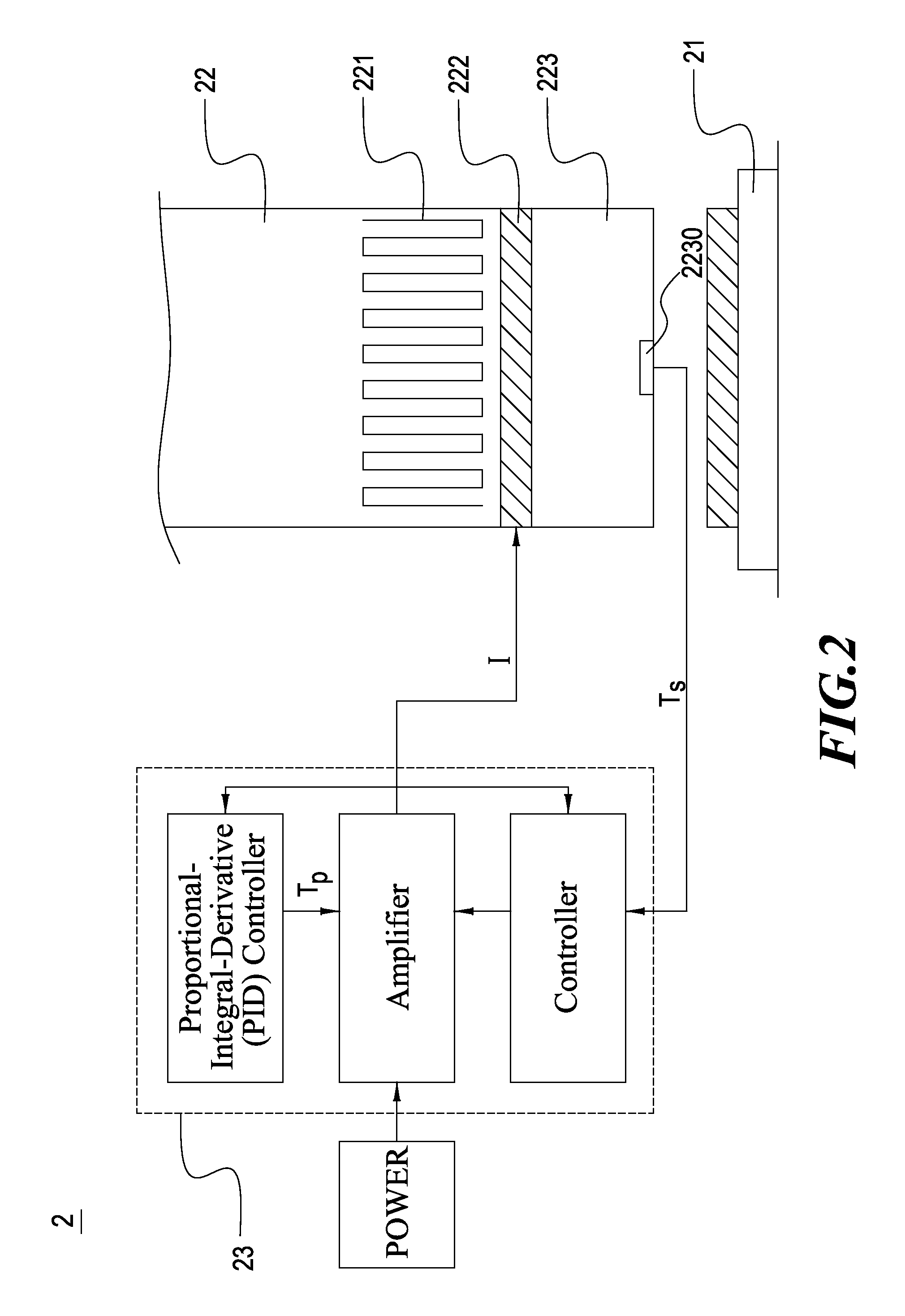
[0018]Refer now to FIG. 2, wherein an architecture diagram of a temperature control system for IC tester in accordance with the present invention is shown. It can be seen from the Figure that the temperature control system for IC tester 2 mainly comprises a test socket 21; a compressing device 22 including a heat exchanger 221 and a thermoelectric cooler (TEC) 222; and a test head 223 having a temperature sensor 2230 and installed at the front end of the compressing device 22. Therefore, upon placing at least one device under test (DUT) onto the test socket 21, the test head 223 coerces tightly one of the DUTs through downward pressure from the compressing device 22 thereby allowing the temperature sensor to ...


PUM


Abstract

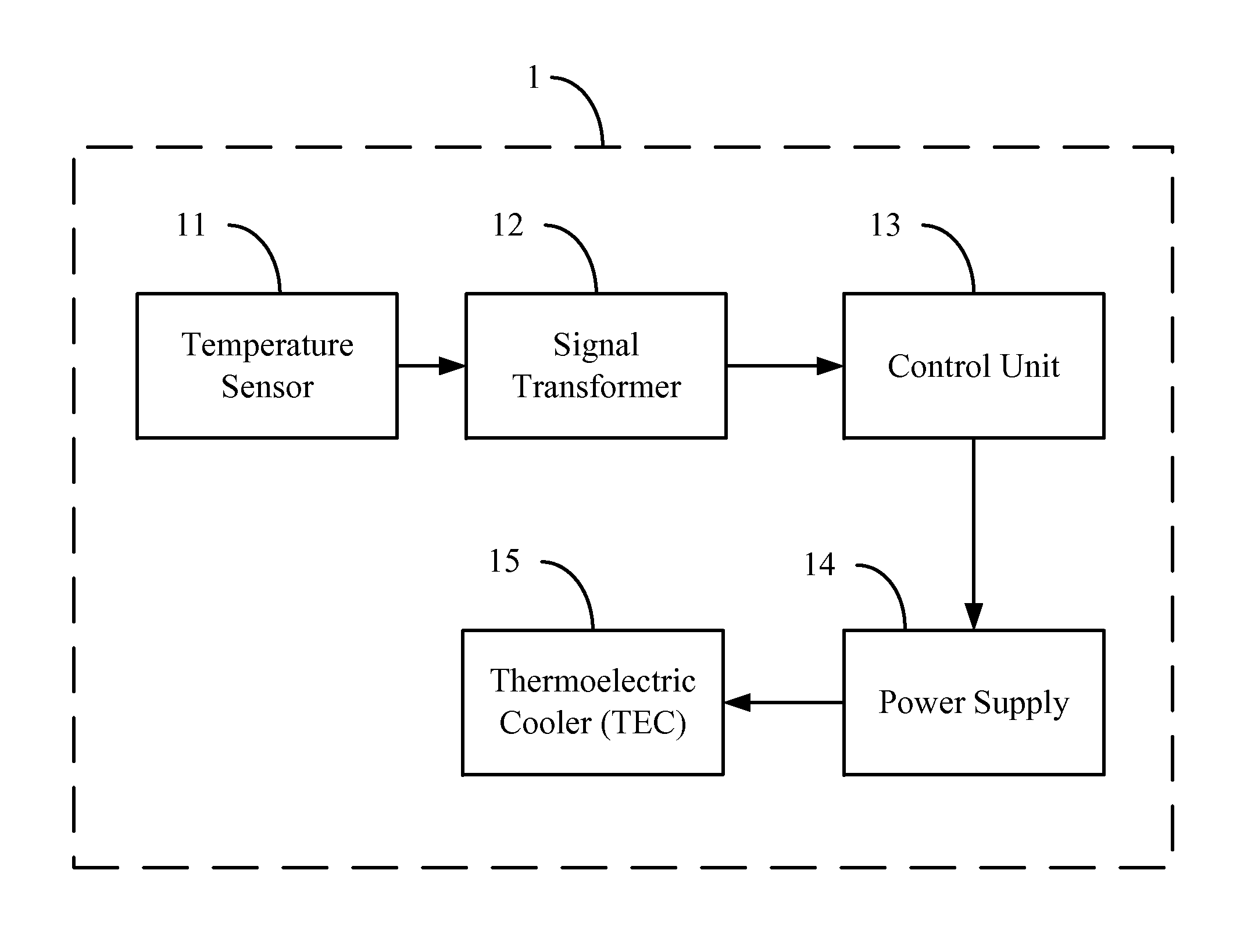
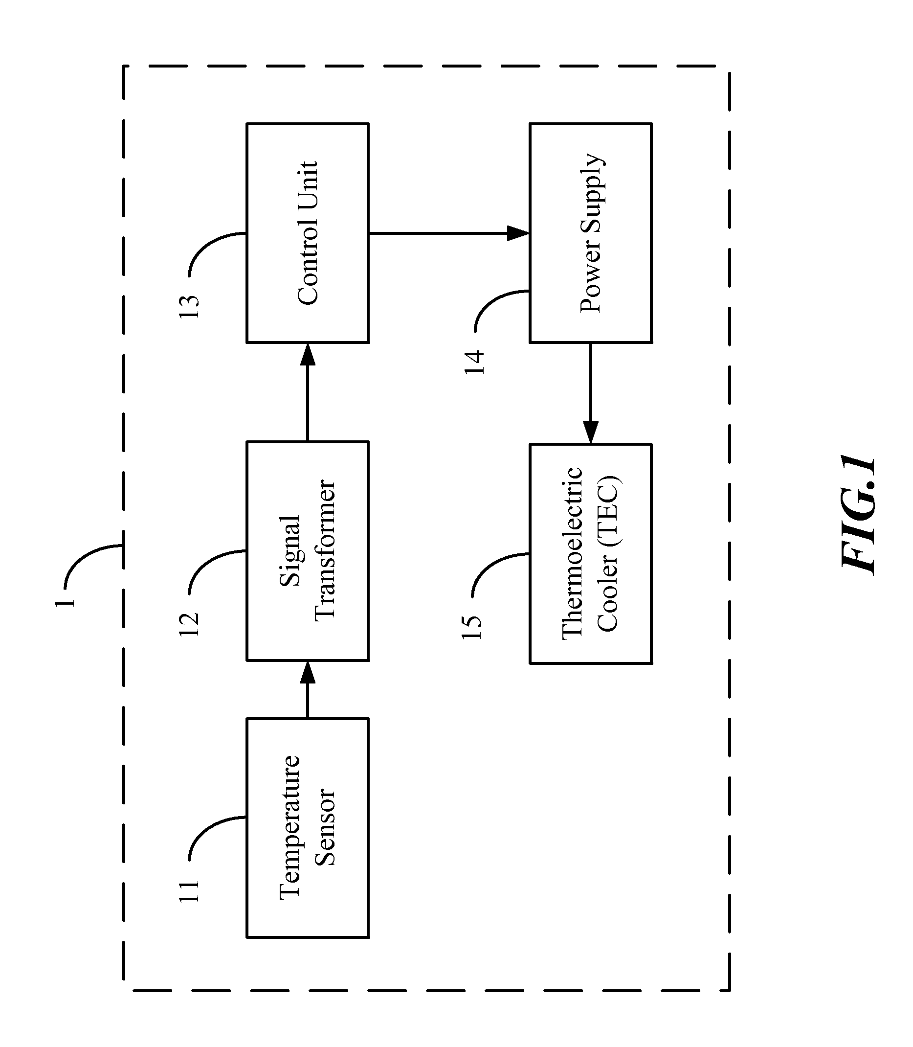
A temperature control system for IC tester, comprising: a test socket; a compressing device including a heat exchanger and a thermoelectric cooler (TEC); and a test head having a temperature sensor. The test head is configured at the front end of the compressing device such that, upon placing at least one device under test (DUT) onto the test socket, the test head coerces tightly one of the DUTs through downward pressure from the compressing device thereby allowing the temperature sensor to detect the surface temperature of the DUT to obtain a temperature signal, and then feed such a temperature signal back to a control processing unit for operations to generate a linear control signal thus that, through the control of the linear control signal, the heat absorption and heat discharge functions of the TEC are enabled to further control the temperature of the DUT within a determined range.

Description

BACKGROUND OF THE INVENTION[0001]1. Field of the Invention[0002]The present invention generally relates to a temperature control system for IC tester; in particular, the present invention relates to a temperature control system for effectively controlling the temperature of a device under test (DUT) within a determined temperature range during tests on the electronic device.[0003]2. Description of Related Art[0004]Integrated circuit (IC) devices allow to integrate and miniaturize massive electronic circuit components and computation speeds as well as product performances thereof are still incessantly elevated, so computational operations requiring combinations of many large-scaled electronic circuits to be successfully completed in the past can be entirely done by such IC devices. Seeing that the IC component yield may directly impact the performance, lifespan and reliability of such types of electronic devices, for IC manufacture, package and test industries, therefore, electric or...

Claims


Application Information

Patent Timeline
IPC IPC(8): G01R31/00
CPCG01R31/2874
Inventor WU, XIN-YICHOU, JUI-CHELU, MENG-KUNGOU YANG, CHIN-YI
Owner CHROMA ATE
Learn More