

Optical intensity-to-phase converter, mach-zehnder interferometer, optical a/d converter, and method of constructing optical intensity-to-phase converter
a technology of optical intensity and phase converter, which is applied in the field of optical intensitytophase converter, machzehnder interferometer, optical a/d converter, and method of constructing optical intensitytophase converter, to achieve the effect of simple configuration of optical a/d converter
- Summary
- Abstract
- Description
- Claims
- Application Information
AI Technical Summary
Benefits of technology
Problems solved by technology
Method used
Image

Examples
first exemplary embodiment
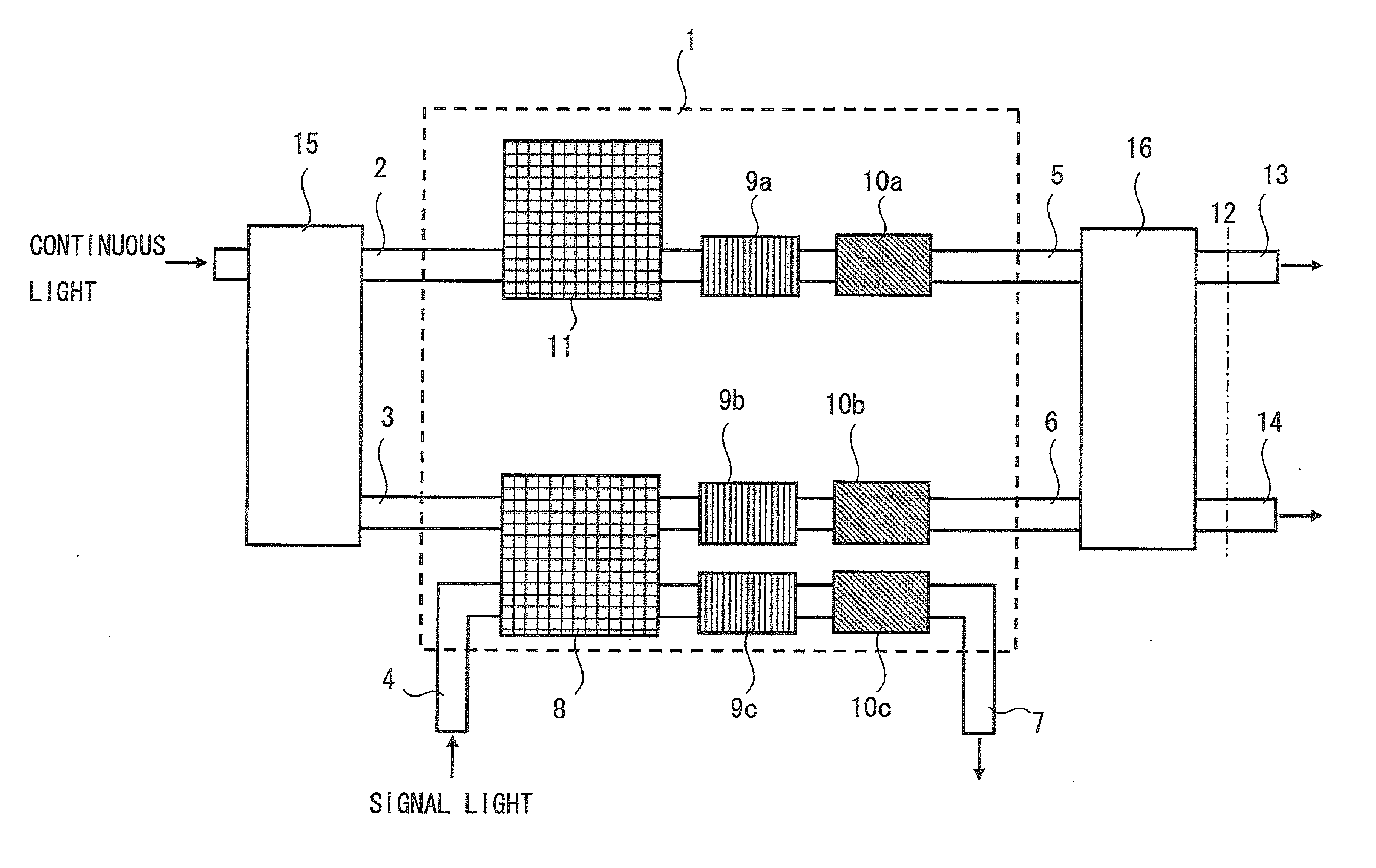
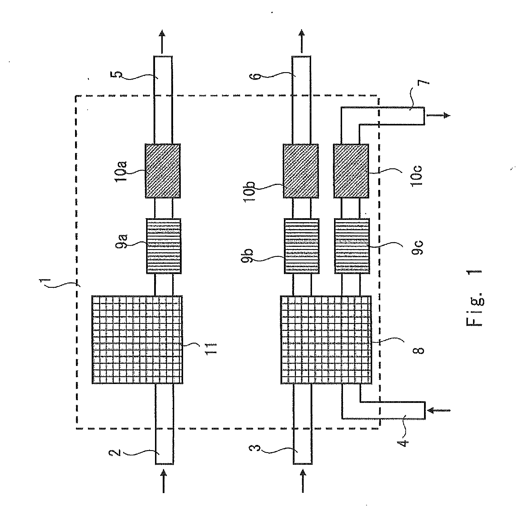
[0042]FIG. 1 is a block diagram of an optical intensity-to-phase converter according to a first exemplary embodiment. The optical intensity-to-phase converter converts information on optical intensity into information on delay. As shown in FIG. 1, this optical intensity-to-phase converter 1 includes an optical coupler / splitter 8 having two inputs and two outputs that is connected to two input ports 3 and 4 and two output ports 6 and 7, an optical coupler / splitter 11 that is connected to the input port 2 and the output port 5, optical intensity adjusters 9a, 9b, and 9c, optical phase adjusters 10a, 10b, and 10c, and optical waveguides that connect them. In FIG. 1, all of the optical coupler / splitter, the optical intensity adjuster, and the optical phase adjuster are provided to each of three paths (first to third waveguides). However, the optical coupler / splitter 11, the optical intensity adjusters 9a, 9b, and 9c, and the optical phase adjusters 10a, 10b, and 10c are not necessary.
[0...
second exemplary embodiment
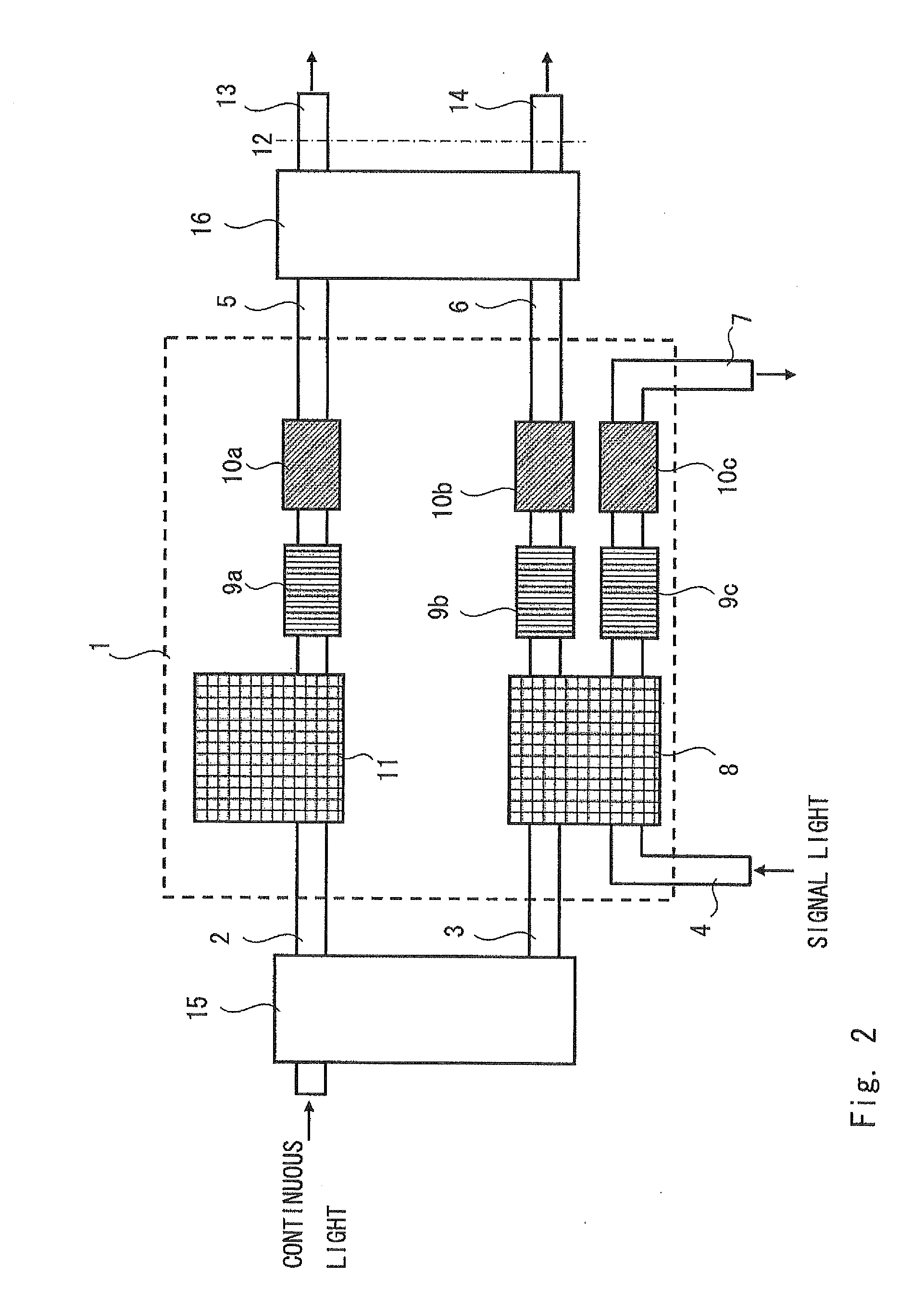
[0054]Next, a second exemplary embodiment is explained with reference to FIG. 2. FIG. 2 is a block diagram of an MZ interferometer according to the second exemplary embodiment and is an example of incorporating the optical intensity-to-phase converter 1 in FIG. 1 to the MZ interferometer. Note that in addition to the optical intensity-to-phase converter 1 in FIG. 1, this MZ interferometer includes an optical splitter 15 and an optical coupler / splitter 16. The same components as those in FIG. 1 are denoted by the same reference numerals, and the explanation is omitted as appropriate.
[0055]First, a continuous light is introduced into the optical splitter 15 as a local light and split into two. Although the optical splitter 15 in FIG. 2 uses the MMI waveguide with two inputs and two outputs, other means may be used such as the MMI waveguide with one input and two inputs or an optical directional coupler. In this case, an absolute value of the amount of phase shift for each port to be o...
third exemplary embodiment
[0060]Next, a third exemplary embodiment is explained with reference to FIG. 4. FIG. 4 is a block diagram of an MZ interferometer according to the third exemplary embodiment and is an example of incorporating the optical intensity-to-phase converter in FIG. 1 to the MZ interferometer. The difference from the MZ interferometer in FIG. 2 according to the second exemplary embodiment is that the positional relationship between the port for introducing the signal light and the port for introducing the continuous light is reversed. Specifically, while the continuous light is input to the input ports 2 and 3 in FIG. 2, the signal light is input to the input ports 2 and 3 in FIG. 4. Moreover, while the signal light is input to the input port 4 in FIG. 2, the continuous light is input to the input port 4 in FIG. 4. Also in the third exemplary embodiment, changes in the signal light as in FIG. 5 can be obtained by adjusting each of the optical coupler / splitter 8, the optical intensity adjuste...
PUM
| Property | Measurement | Unit |
|---|---|---|
| bandgap wavelength | aaaaa | aaaaa |
| bandgap wavelength | aaaaa | aaaaa |
| size | aaaaa | aaaaa |
Abstract
Description
Claims
Application Information