Detecting device for detecting icing by image and detecting method thereof

a detection device and image technology, applied in the field of image ice detection devices, can solve the problems of affecting the performance and application scope, affecting the accuracy of image enhancement, and complicated structure, and achieve the effect of avoiding or reducing errors of detection

Inactive Publication Date: 2013-05-09
COMAC +2
View PDF11 Cites 36 Cited by
  • Summary
  • Abstract
  • Description
  • Claims
  • Application Information

AI Technical Summary

Benefits of technology

[0046]Preferably, the image is divided into a plurality of areas, and ice conditions are judged for each of the areas. As such, results of the plurality of areas may be compared to avoid or reduce mistakes and errors of detection.

Problems solved by technology

However, these already existing ice detecting devices and methods all have their respective drawbacks and shortcomings and therefore greatly affect the performance and application scope thereof.
For example, ice detecting devices and method in the early period includes a radiation type, an electrical conductivity type and a differential pressure type, wherein the radiation type ice detecting device and method causes serious harm to people's health, the electrical conductivity type ice detecting device and method exhibits an undesirable reliability, and the differential pressure type ice detecting device and method is disadvantageous in a large size, a complicated structure and a slow response speed.
Besides, these several kinds of ice detecting devices and methods can only present qualitative detecting results of whether the ice is formed and cannot present quantitative information about ice thickness and the icing speed.
However, they have their respective drawbacks: the detector as used in the magnetostrictive vibration barrel type ice detecting method exhibits a complicated structure, high requirements for production process and difficult calibration, and cannot be mounted at a curved surface position (e.g., the front edge of the airfoil and tail fin of the airplane) in a flush and shape-preserving manner; the detector used in the piezoelectric diaphragm type ice detecting method has a smaller size and weight and can be mounted at a cured surface position in a flush and shape—preserving manner to a certain degree, but the sensitive material thereof imposes rigid production requirements and complex process and the assembling thereof is difficult.
However, the optical fiber type ice detector has the following drawbacks: first, it cannot achieve detection of supercooled large droplet icing (hereinafter referred to as SLD); secondly, it cannot eliminate or completely eliminate the influence exerted by the types of ice on quantitative analysis; besides, it can only achieve point detection and cannot detect a surface with larger dimensions.
However, kernel sensing and detecting elements of these detectors still employ magnetostrictive resonant type and piezoelectric icing sensors, so they inevitably have common drawbacks of the conventional ice detectors as mentioned above.
With regard to accurate recognition of types of ice, although the detectors in the prior art can achieve judgment of the types of ice to some degree, but the accuracy thereof is relatively low.

Method used


Image

  • Detecting device for detecting icing by image and detecting method thereof
  • Detecting device for detecting icing by image and detecting method thereof
  • Detecting device for detecting icing by image and detecting method thereof

Examples


Embodiment Construction

[0057]Preferred embodiments of the present invention will be described in detail with reference to the figures.

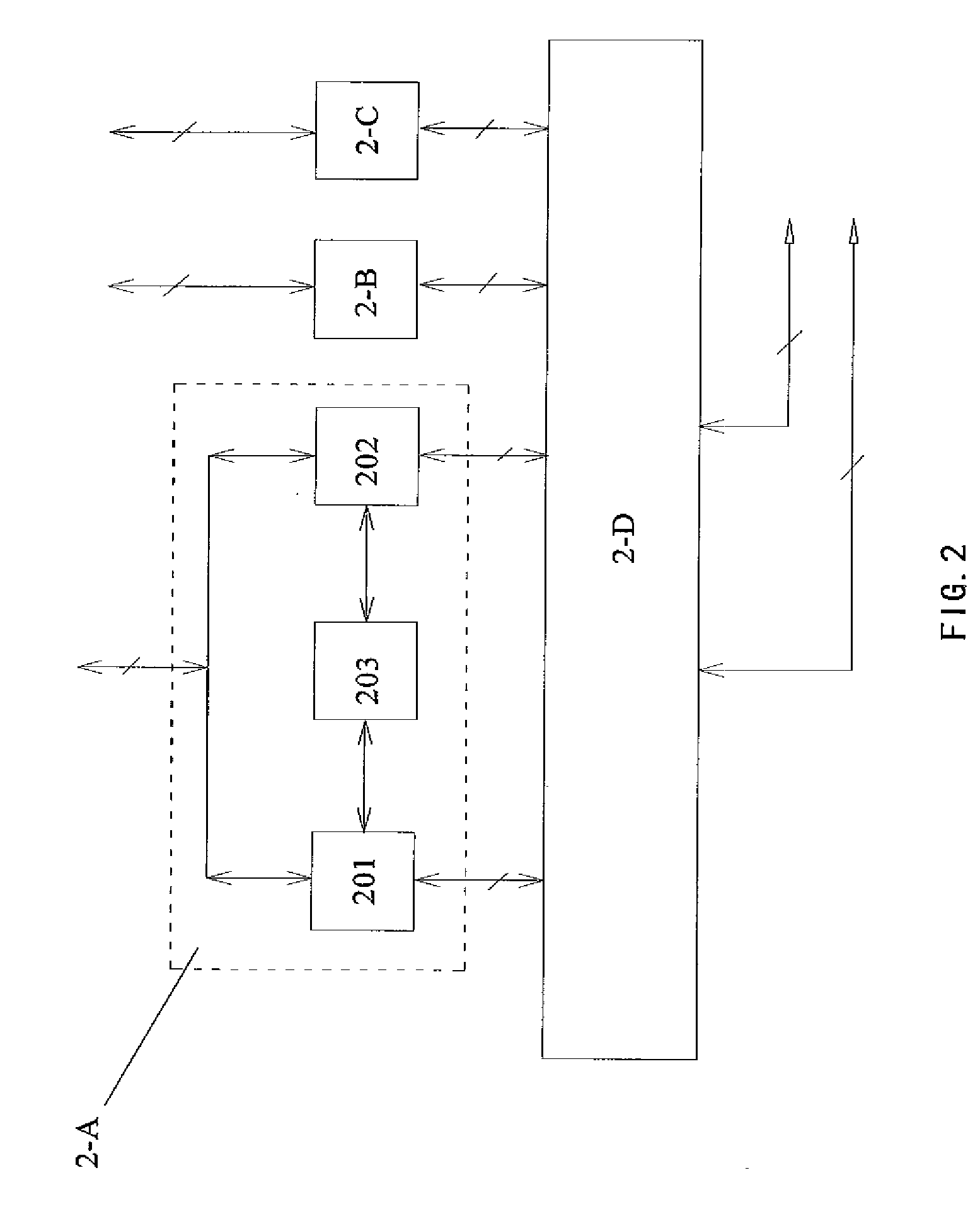
[0058]An image ice detector according to a first preferred embodiment of the present invention mainly comprises an image acquiring system and an image processing system, wherein the former is configured to acquire images from the surface of the object, and then the latter calculates and analyzes the acquired surface images so as to finally obtain the ice conditions of the surface of the object.

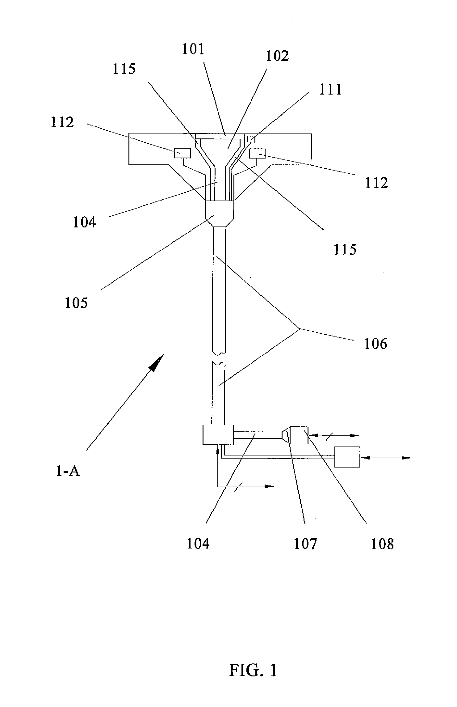
[0059]First referring to FIG. 1, what is shown is an image acquiring system 1-A of the image ice detector according to the first preferred embodiment of the present invention.

[0060]A kernel part of the image acquiring system 1-A is an image-transmitting optical fiber harness 104 which is configured to receive the surface image of the object at a front end thereof and transmit the surface image along the optical fibers therein to other parts connected at a rear end thereof. The structu...


PUM


Abstract

A detecting device for detecting icing by an image includes an image acquiring system (1-A) and an image processing system (2-A). The image acquiring system (1-A) can acquire an image of an object's surface. The image processing system (2-A) can analyze the image and obtain an icing condition of the object's surface. The detecting device is simple and reliable. It can identify the category of the icing effectively. So, it can improve the accurateness of the icing detection significantly and can accomplish the detection of the object's whole surface. Furthermore, it can detect an icing condition of a super-cooled large droplet. A method for detecting an icing condition of an object's surface using the detecting device is also provided.

Description

FIELD OF THE INVENTION[0001]The present invention relates to an image ice detecting device and a detecting method for obtaining information about ice conditions on a surface of an object by analyzing images of the surface of the object, including whether ice is formed, type of ice, thickness and / or area of the ice or the like.BACKGROUND OF THE INVENTION[0002]In most cases, there is a need to detect or analyze ice conditions on a particular surface or position of the object. For example, in a cold region, there is a need to monitor the ice conditions on road surface in winter, to detect the ice conditions of blade and partial rotating members of a wind turbine, and monitor icing phenomena at many positions of an airplane (e.g., a wind shield, a front edge of an airfoil and a tail fin, and an air intake duct of an engine) during flight of the airplane to avoid adverse influence caused by the ice on the airplane, and prevent serious airplane flight accident caused by the ice. Noticeabl...

Claims


Application Information

Patent Timeline
Patent Type & Authority Applications(United States)
IPC IPC(8): B64D15/20
CPCB64D15/20G06T2207/30156G06T7/401G06T7/0004G06T7/41
Inventor CHEN, YINGCHUNYE, LINZHANG, MIAOGE, JUNFENGFENG, LIJUANLIU, TIEJUNZHOU, FENG
Owner COMAC
Why Eureka
Try Eureka