Reflective panel for solar power generation

a solar energy and solar thermal technology, applied in the direction of heat collector mounting/support, lighting and heating equipment, instruments, etc., can solve the problems of low energy density, difficult storage and transportation of solar energy, and the recovery efficiency of solar energy has not yet reached the level of sufficient level, so as to facilitate transportation, assembly and maintenance, and operate with less power consumption

Inactive Publication Date: 2013-05-09
KONICA MINOLTA OPTO
View PDF5 Cites 21 Cited by
  • Summary
  • Abstract
  • Description
  • Claims
  • Application Information

AI Technical Summary

Benefits of technology

[0011]An object of the present invention is to provide a reflector for solar thermal power generation and a reflection device for solar thermal power generation which are lightweight and provide ease of transportation, assembly, and maintenance including replacement and can operate with less power consumption.

Problems solved by technology

(1) Solar energy has a low energy density.
(2) Solar energy is difficult to store and transport.
However, the recovery efficiency thereof has not yet reached the enough level.
However, large glass mirrors composed of thin glass base materials can be damaged in the process of installation or can be broken by objects flying in strong wind.
If the thickness of the glass base materials is increased, the glass mirrors become very heavy and are difficult to handle at installation.
Moreover, the transportation cost thereof is increased.
Accordingly, if the weight of the reflectors is increased, the driving power of the reflectors is increased, the power consumption for driving the same is increased, and the solar thermal power generation therefore becomes inefficient.
However, the metal base materials have high elasticity and high specific gravity.
If the metal base materials are made thin for the purpose of weight reduction, the metal materials do not have self-supporting property.
Accordingly, the power consumption for tracking the sun cannot be reduced.
On the other hand, if the metallic base materials are made thick for the self-supporting property, the reflectors become heavy, and the power consumption for tracking the sun cannot be reduced.

Method used


Image

  • Reflective panel for solar power generation
  • Reflective panel for solar power generation
  • Reflective panel for solar power generation

Examples


example 1

Production of Light Collecting Mirror

(Production of Film Mirror)

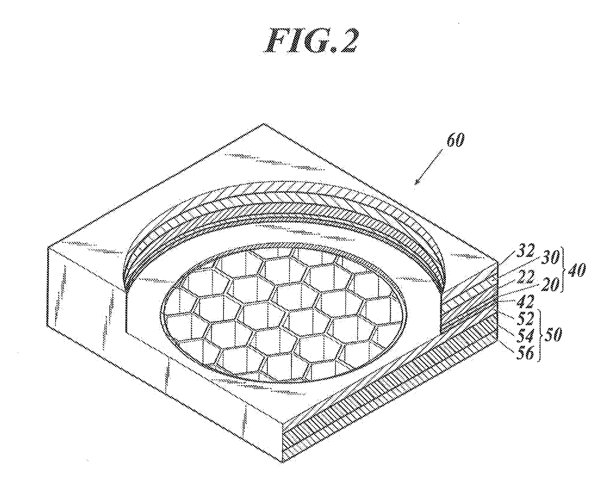
[0093]As the flexible supporting body 20, bi-axially oriented polyester film (polyethylene terephthalate film, 100 μm thick) was used. One side of the polyethylene terephthalate film is coated with resin by gravure coating so that a 0.1 μm thick adhesive layer was formed. The coating resin contained polyester resin (POLYESTER SP-181, Nippon Synthetic Chemical Industry, Co., Ltd), melamine resin (Super Beckamine J-820, DIC corporation), TDI isocyanate (2,4-tolylene diisocyanate), HDMI isocyanate (1,6-hexamethylene diisocyanate) which were mixed into toluene at a resin solid content ratio of 20 / 1 / 1 / 2 with a solid content concentration of 10%. On the surface opposite to the adhesive layer 48, a 80 nm-thick silver reflective layer was formed by vacuum vapor deposition as a silver reflective layer, which was then coated by gravure coating with resin containing polyester resin and TDI (tolylene diisocyanate) isocianate mixed ...


PUM


Abstract

A reflector for solar thermal power generation includes a light collecting mirror attached to a self-supporting base material. The light collecting mirror includes at least: a flexible supporting body; and a light/heat reflective layer provided on at least one side of the supporting body. The self-supporting base material has any one of configurations A and B below: A: the base material includes a pair of metallic plates and an intermediate layer provided between the metallic plates, the intermediate layer being a layer having a hollow structure or a layer composed of a resin material; and B: the base material is composed of a resin material layer having a hollow structure.

Description

CROSS REFERENCE TO RELATED APPLICATION[0001]This is a continuation Application (CA) of International Application No. PCT / JP2011 / 063791 filed on Jun. 16, 2011 which claims priority to Japanese Patent Application No. 2010-144801 filed on Jun. 25, 2010. The disclosure of each of the prior applications is hereby incorporated by reference in its entirety.BACKGROUND OF THE INVENTION[0002]1. Field of the Invention[0003]The present invention relates to a reflector for solar thermal power generation and, more specifically, relates to a reflector for solar thermal power generation and a reflection device for solar thermal power generation which are lightweight, provide ease of transportation, assembly, and maintenance including replacement, and can be used with less power consumption.[0004]2. Description of Related Art[0005]In recent years, uses of natural energy are being considered as energy alternative to fossil fuel energy including oil and natural gas. Among the natural energy, solar ene...

Claims


Application Information

Patent Timeline
Patent Type & Authority Applications(United States)
IPC IPC(8): G02B5/10F24S23/70
CPCG02B5/08G02B5/10F24J2002/1076F24J2/1052F24J2/1057Y02E10/40G02B5/0808F24S2025/601F24S2023/87F24S23/82F24S23/81
Inventor EGURO, YAYOI
Owner KONICA MINOLTA OPTO
Why Eureka
Try Eureka