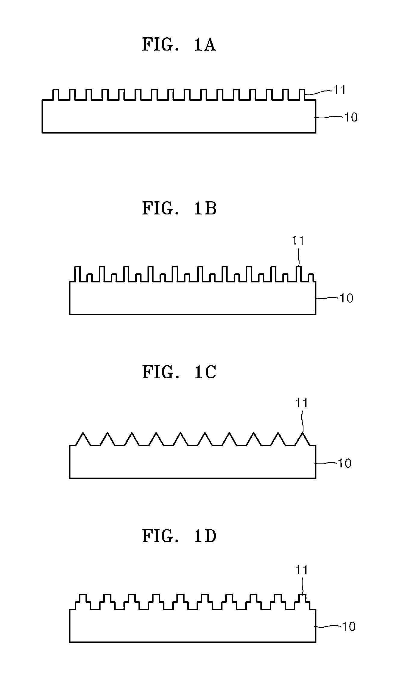
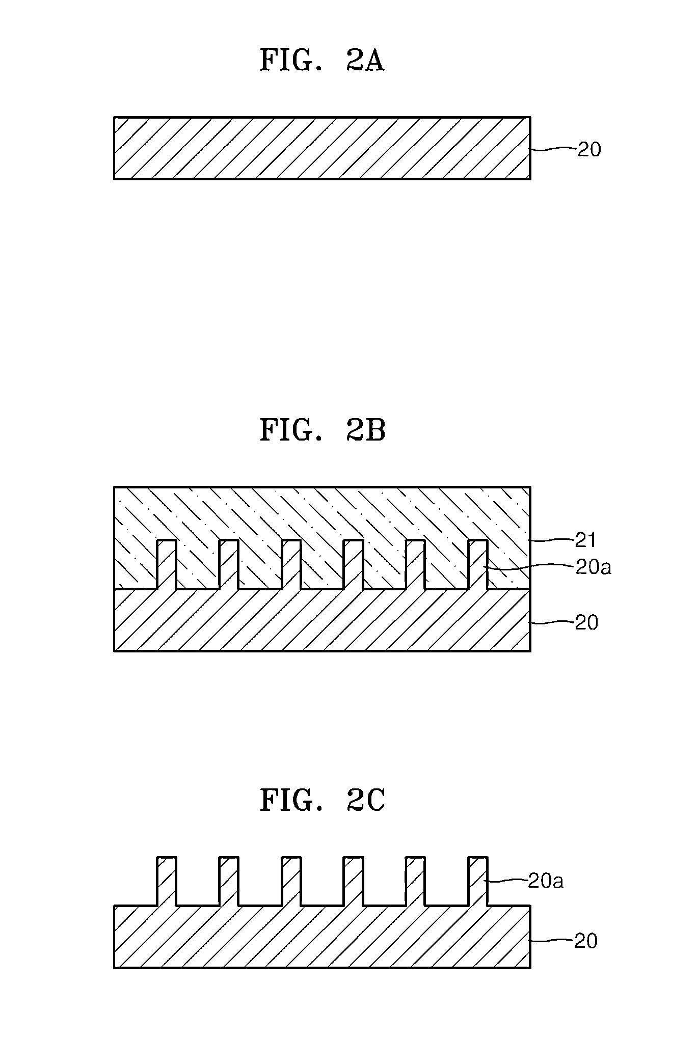
NANO composite with superhydrophobic surface and method of manufacturing the same

Inactive Publication Date: 2013-05-09
SAMSUNG ELECTRONICS CO LTD
View PDF7 Cites 28 Cited by
  • Summary
  • Abstract
  • Description
  • Claims
  • Application Information

AI Technical Summary

Benefits of technology

[0028]According to another embodiment, the polymer base includes a thermoplastic polymer, and the contacting of the mold to the surface of the nano composite material further inclu

Problems solved by technology

However, if a nano composite is exposed to an outside environment, the nano composit

Method used


Image

  • NANO composite with superhydrophobic surface and method of manufacturing the same
  • NANO composite with superhydrophobic surface and method of manufacturing the same
  • NANO composite with superhydrophobic surface and method of manufacturing the same

Examples


experimental example

[0068]To form a nano composite, a two-part, curable PDMS elastomer (Sylgard 184 SILICONE ELASTOMER BASE, DOW Corning) was used as a curable polymer, whereas multi-wall carbon nanotubes (“MWCNTs”) (Hanhwa Inotech) were used as a nano filler. The MWCNTs had diameters from about 10 nm to about 20 nm, lengths from about 100 μm to about 200 μm, and aspect ratios from about 3,000 to about 20,000 when delivered by the manufacturer. Nano composites were formed by respectively adjusting contents of nanotubes with respect to the overall mass of the nano composites to 1 wt %, 3 wt %, 5 wt %, 7.5 wt %, and 10 wt %. For effective dispersion of nanotubes in the nano composites, a paste mixer (DAE HWA TECH, PDM-1k) was used. Furthermore, 3-roll milling equipment (Ceramic 3 roll mill: INOUE MFG., INC.) was used to disperse nanotubes in the nano composites. Specifically, after the PDMS and the nanotubes were put into a predetermined container, the PDMS and the nanotubes were mixed for about 1 minute...


PUM

PropertyMeasurementUnit
Percent by massaaaaaaaaaa
Widthaaaaaaaaaa

Abstract

A nano composite with superhydrophobic surfaces including a bulk portion and a surface portion having a superhydrophobic pattern, wherein the bulk portion and the surface portion include the same material, and methods of manufacturing of the nano composite.

Description

CROSS-REFERENCE TO RELATED APPLICATIONS[0001]This application claims priority to and the benefit of Korean Patent Application No. 10-2011-0124388, filed on Nov. 25, 2011, and Korean Patent Application No. 10-2012-0039966, filed on Apr. 17, 2012, and all the benefits accruing therefrom under U.S.C. §119, the content of which are incorporated herein in their entirety by reference.BACKGROUND[0002]1. Field[0003]The present disclosure relates to superhydrophobic nano structures, and more particularly, to nano composites with superhydrophobic surfaces and methods of manufacturing the same.[0004]2. Description of the Related Art[0005]A nano composite, such as a carbon nanotube composite, has excellent electrical, mechanical, and electromagnetic properties. For example, if a polymer nano composite is formed by combining a polymer, which is an insulator having weak mechanical strength, with nano materials, such as carbon nanotubes, carbon fibers, graphene, etc., properties of the polymer may...

Claims


Application Information

Patent Timeline
IPC IPC(8): B32B3/30
CPCB32B3/30Y10T428/24355B82Y30/00B82B1/008C08K3/041C01B32/158
Inventor PARK, SUNG-HOONCHO, EUN-HYOUNGSOHN, JIN-SEUNGKIM, DONG-EARNKIM, DONG-OUKKIM, HA-JINBAE, MIN-JONGSON, YOON-CHULLEE, SANG-EUICHU, KUN-MO
Owner SAMSUNG ELECTRONICS CO LTD
Why Eureka
Try Eureka