Marine vessel propulsion device

Active Publication Date: 2013-05-09
YAMAHA MOTOR CO LTD
View PDF5 Cites 16 Cited by
  • Summary
  • Abstract
  • Description
  • Claims
  • Application Information

AI Technical Summary

Benefits of technology

[0029]According to this arrangement, the power generation coil is attached to the rim, and the illuminant is connected to the power generation coil. At least one portion of the power generation coil faces the stator. Therefore, when the electric motor rotates the propeller (the rim), a magnetic flux passing through the power generation coil changes, and an electric current (an induced current) is generated in the power generation coil. As a result, the illuminant emits light. The electric current generated in the power generation coil changes in accordance with the rotation speed of the propeller. Additionally, when the propeller is rotated with a high torque, electric power supplied to the stator is g

Problems solved by technology

Therefore, the structure of the marin

Method used


Image

  • Marine vessel propulsion device
  • Marine vessel propulsion device
  • Marine vessel propulsion device

Examples


Example

[0084]Propellers according to the following preferred embodiments are preferably rotatable in a normal rotation direction and in a reverse rotation direction. The normal rotation direction may be a clockwise direction (i.e., right-handed rotation direction) when the propeller is seen from behind, or may be a counterclockwise direction (i.e., left-handed rotation direction) when the propeller is seen from behind. Hereinafter, the clockwise direction of the propeller seen from behind is defined as the normal rotation direction of the propeller, and the counterclockwise direction of the propeller seen from behind is defined as the reverse rotation direction of the propeller.

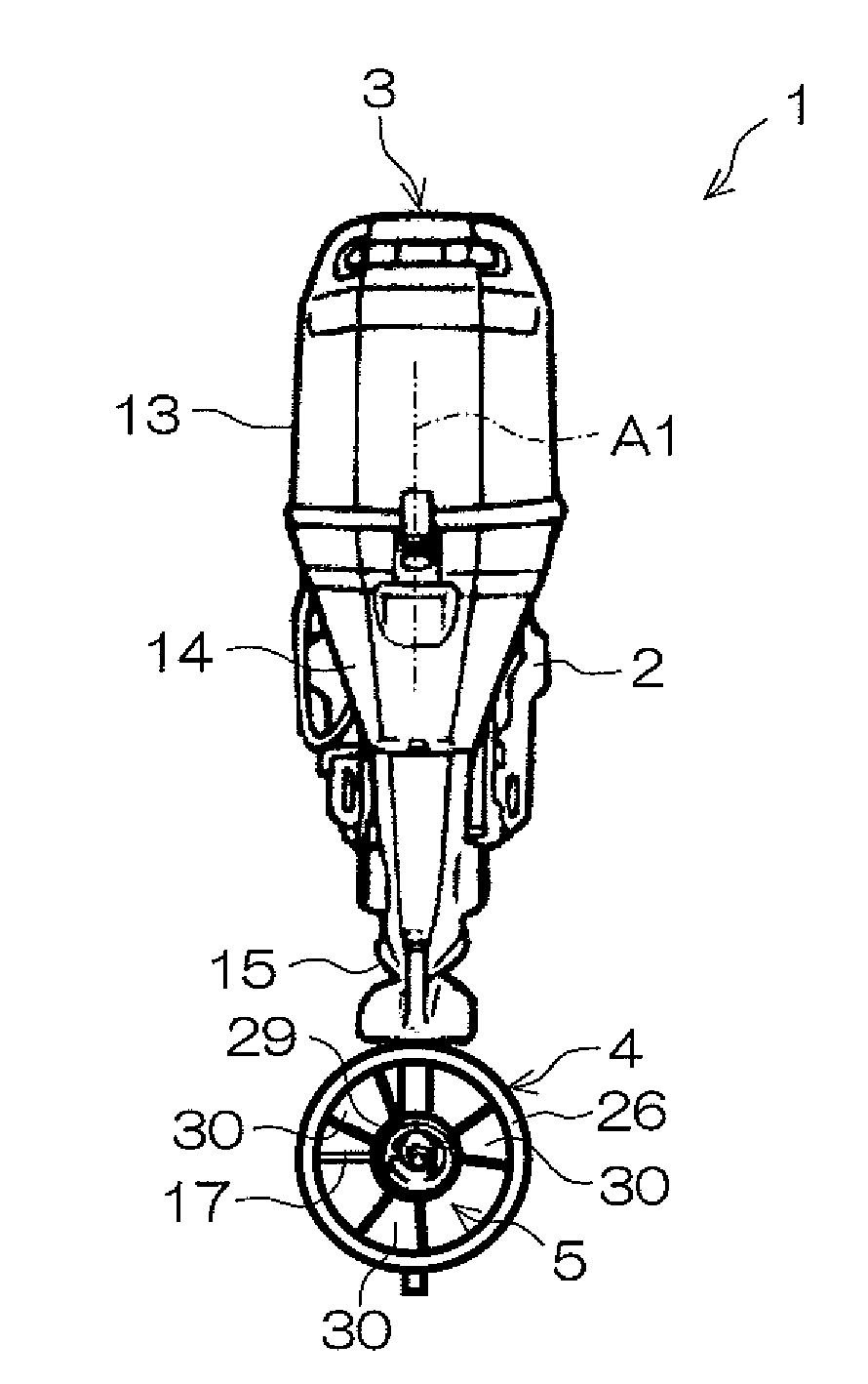
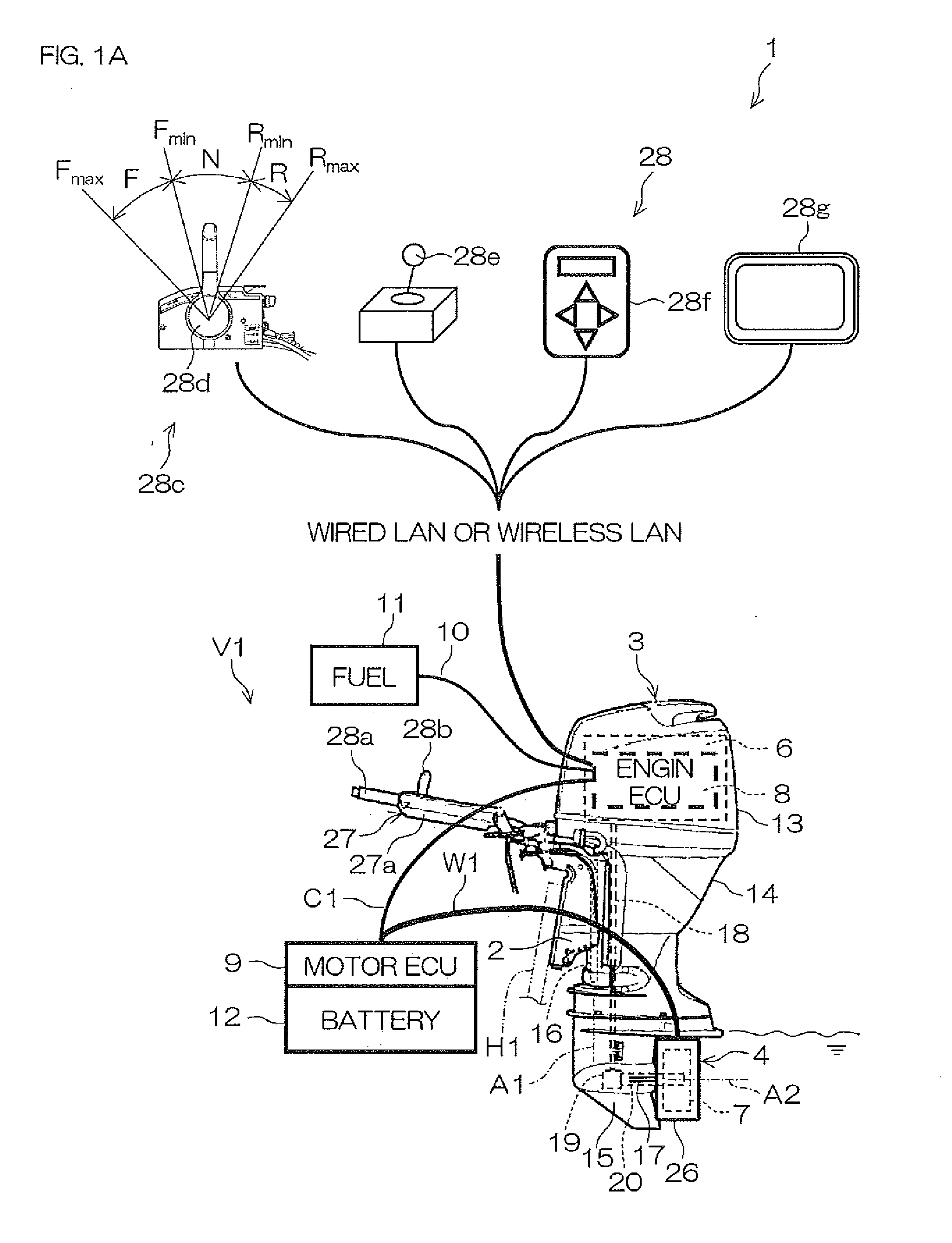
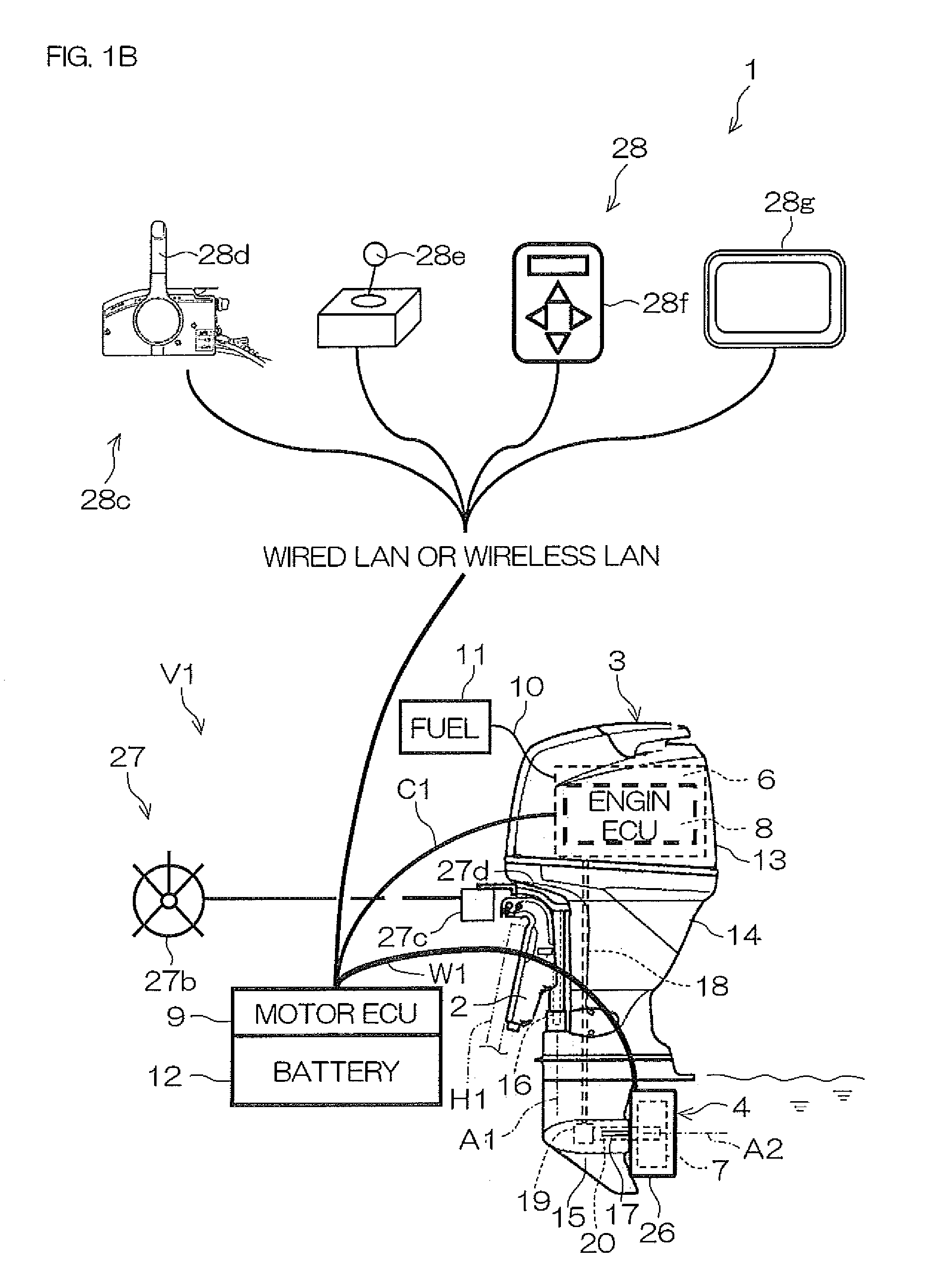
[0085]FIG. 1A and FIG. 1B are side views of a marine vessel propulsion device 1 according to a first preferred embodiment of the present invention. FIG. 2 is a rear view of the marine vessel propulsion device 1 according to the first preferred embodiment of the present invention. FIG. 3 is a schematic view of a forw...


PUM


Abstract

A marine vessel propulsion device includes a propeller rotatable around a propeller axis, a duct that surrounds the propeller around the propeller axis, an internal combustion engine that rotates the propeller relative the duct, and an electric motor that rotates the propeller relative to the duct. The propeller includes a plurality of blades, and a cylindrical rim that surrounds the plurality of blades around the propeller axis. The electric motor rotates the propeller by rotating the rim.

Description

BACKGROUND OF THE INVENTION[0001]1. Field of the Invention[0002]The present invention relates to a marine vessel propulsion device.[0003]2. Description of the Related Art[0004]A hybrid type marine vessel propulsion device including an engine (internal combustion engine) and an electric motor has been disclosed.[0005]For example, United States Patent Application Publication Number US 2008 / 0113569 A1 discloses amarine vessel propulsion device that includes an outboard motor having a built-in engine and a built-in electric motor. The engine is connected to a propeller through a drive shaft, a forward / rearward switching mechanism, and a propeller shaft. The electric motor is placed on the drive shaft between the engine and the forward / rearward switching mechanism. The engine is connected to the electric motor through a multi-plate clutch placed on the drive shaft. When the propeller is driven by the engine, the multi-plate clutch is engaged, and, when the propeller is driven by the elec...

Claims


Application Information

Patent Timeline
IPC IPC(8): B63H21/20B63H21/21B63H23/02B63H5/14
CPCB63H21/14B63H21/17Y02T70/5236B63H2021/205B63H21/20B63H1/16B63H20/007B63H2023/005
Inventor SUZUKI, TAKAYOSHIHIRAOKA, NORIYOSHI
Owner YAMAHA MOTOR CO LTD
Why Eureka
Try Eureka