Marine vessel propulsion device

a propulsion device and vessel technology, applied in marine propulsion, vessel parts, vessel construction, etc., can solve the problems of increasing the size of the lower case containing the bevel gear, the diameter of the rotor can be enlarged, and the output of the electric motor can be increased, so as to prevent the reduction of propulsive efficiency, the effect of reducing the size of the rotor and reducing the size of the bevel gear

Active Publication Date: 2013-05-09
YAMAHA MOTOR CO LTD
View PDF8 Cites 21 Cited by
  • Summary
  • Abstract
  • Description
  • Claims
  • Application Information

AI Technical Summary

Benefits of technology

[0006]In the arrangement of Japanese Unexamined Patent Application Publication No. 2009-234513, the electric motor is disposed in the water in front of the propeller, and therefore the effective area of the propeller is decreased, and propulsive efficiency is lowered. Additionally, the rotation of the electric motor is transmitted to the propeller without being decelerated. Therefore, when the maximum value of torque to be applied to the propeller is increased, there is a need to use a high-output electric motor, and the electric motor becomes large in size. Therefore, the effective area of the propeller is further decreased, and the resistance of the water applied to a casing with which the electric motor is covered is increased. Therefore, the propulsive efficiency is further lowered.
[0032]According to this arrangement, the power generation coil is attached to the rim, and the illuminant is connected to the power generation coil. At least one portion of the power generation coil faces the stator. Therefore, when the electric motor rotates the propeller (the rim), a magnetic flux passing through the power generation coil changes, and an electric current (an induced current) is generated in the power generation coil. As a result, the illuminant emits light. The electric current generated in the power generation coil changes in accordance with the rotation speed of the propeller. Additionally, when the propeller is rotated with a high torque, electric power supplied to the stator is greater than with a low torque even if the rotation speed of the propeller is the same, and therefore the electric current generated in the power generation coils is increased. Therefore, the light emission state of the illuminant changes in accordance with the rotation state of the propeller including its rotation speed and torque. A member (power generation coil) that rotates together with the propeller generates electric power in this way, and therefore electric power can be reliably supplied to the illuminant even if the illuminant is disposed on the propeller. In other words, there is no need to provide complex wiring that extends from a fixing portion (duct) to a rotational body (propeller).

Problems solved by technology

Therefore, when the maximum value of torque to be applied to the propeller is increased, there is a need to use a high-output electric motor, and the electric motor becomes large in size.
However, an increase in the reduction gear ratio of the bevel gears leads to an increase in the size of the bevel gears, and therefore a lower case containing the bevel gears becomes large in size.

Method used


Image

  • Marine vessel propulsion device
  • Marine vessel propulsion device
  • Marine vessel propulsion device

Examples


Embodiment Construction

[0072]Propellers according to the following preferred embodiments are preferably rotatable in a normal rotation direction and in a reverse rotation direction. The normal rotation direction may be a clockwise direction (i.e., right-handed rotation direction) when the propeller is seen from behind, or may be a counterclockwise direction (i.e., left-handed rotation direction) when the propeller is seen from behind. Hereinafter, the clockwise direction of the propeller seen from behind is defined as the normal rotation direction of the propeller, and the counterclockwise direction of the propeller seen from behind is defined as the reverse rotation direction of the propeller.

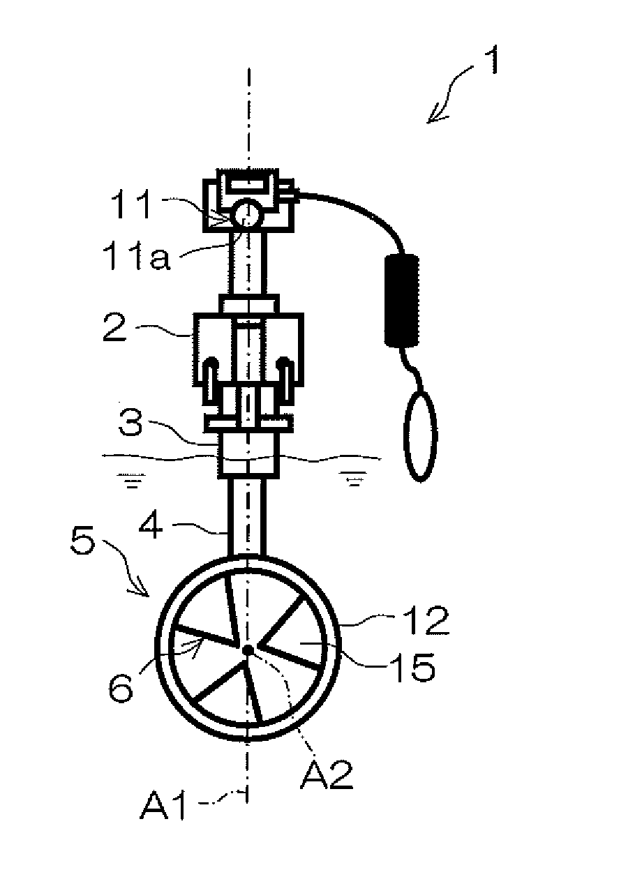
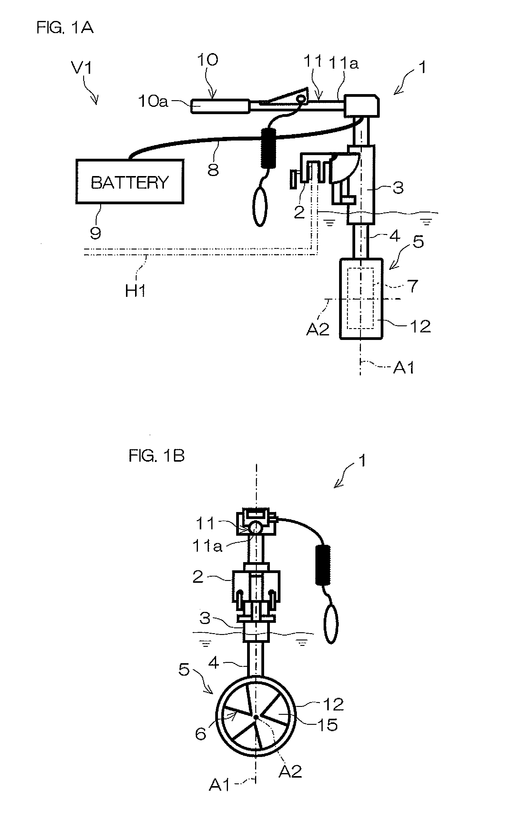
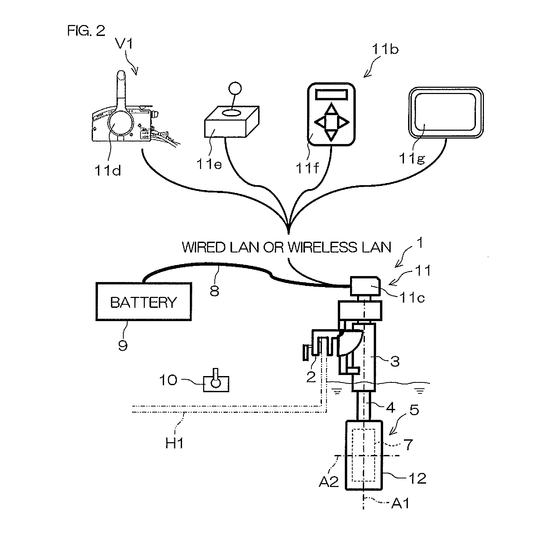
[0073]FIG. 1A is a side view of a marine vessel propulsion device 1 according to a first preferred embodiment of the present invention, and FIG. 1B is a front view of the marine vessel propulsion device 1 shown in FIG. 1A. FIG. 2 is a side view of the marine vessel propulsion device 1 according to the first preferre...


PUM


Abstract

A marine vessel propulsion device includes a bracket that is attachable to a marine vessel, a duct that is rotatable around a steering axis with respect to the bracket, a propeller that is rotatable with respect to the duct around a propeller axis extending in a direction perpendicular or substantially perpendicular to the steering axis, and an electric motor that rotates the propeller. The propeller includes a plurality of blades and a cylindrical rim that surrounds the plurality of blades, and is surrounded by the duct. The electric motor rotates the rim with respect to the duct.

Description

BACKGROUND OF THE INVENTION[0001]1. Field of the Invention[0002]The present invention relates to a marine vessel propulsion device.[0003]2. Description of the Related Art[0004]A marine vessel propulsion device provided with an outboard motor into which an engine (internal combustion engine) is built has been known. Japanese Unexamined Patent Application Publication No. 2005-153727 and Japanese Unexamined Patent Application Publication No. 2009-234513 disclose an electrically-operated marine vessel propulsion device provided with an outboard motor into which an electric motor is built instead of an engine. In the electrically-operated marine vessel propulsion device of Japanese Unexamined Patent Application Publication No. 2005-153727, the electric motor is disposed above the surface of the water. In the electrically-operated marine vessel propulsion device of Japanese Unexamined Patent Application Publication No. 2009-234513, the electric motor is disposed in the water in front of a...

Claims


Application Information

Patent Timeline
Patent Type & Authority Applications(United States)
IPC IPC(8): B63H21/17B63H23/06B63H5/10B63H5/14
CPCB63H1/16B63H5/125B63H5/14B63H2023/005B63H23/00B63H2001/165B63H20/00B63H20/007B63H23/24
Inventor SUZUKI, TAKAYOSHIHIRAOKA, NORIYOSHI
Owner YAMAHA MOTOR CO LTD
Why Eureka
Try Eureka