Method for Controlling an Electrohydraulic Braking System and Electrohydraulic Braking System

a technology of electrohydraulic braking and braking system, which is applied in the direction of braking systems, etc., can solve the problems of difficult to set the pressure in the pressure chamber of the piston-cylinder arrangement with a the above described control operation also produces particular noise problems, and permanent adverse effects, etc., to achieve modulation of pressure, high level of accuracy, and high pressure differential across the inlet valve

Active Publication Date: 2013-05-16
CONTINENTAL TEVES AG & CO OHG
View PDF12 Cites 21 Cited by
  • Summary
  • Abstract
  • Description
  • Claims
  • Application Information

AI Technical Summary

Benefits of technology

[0006]The control method described in DE 10 2011 076 675 has the principle disadvantage that it is difficult to set the pressure in the pressure chamber of the piston-cylinder arrangement with a high level of accuracy since in the by far longest time periods of the control operation all inlet valves are closed and consequently the pressure chamber are separated from the relatively elastic wheel brakes. In order to be able to modulate the pressure in a rapid and reproducible manner, the pressure chamber itself is not to have any noticeable elasticity. However, from the point of view of control technology, this boundary condition represents a problem, since even an extremely small modulation of the piston travel causes the pressure in the rigid pressure chamber to fluctuate by amounts that are not insignificant. In addition to the problems associated with control technology, the above described

Problems solved by technology

The control method described in DE 10 2011 076 675 has the principle disadvantage that it is difficult to set the pressure in the pressure chamber of the piston-cylinder arrangement with a high level of accuracy since in the by far longest time periods of the control operation all inlet valves are closed and consequently the pressure chamber are separated from the relatively elastic wheel brakes.
However, from the point of view of control technology, this boundary condition represents a problem, since even an extremely small modulation of the piston travel causes the pressure in the rigid pressure chamber

Method used


Image

  • Method for Controlling an Electrohydraulic Braking System and Electrohydraulic Braking System
  • Method for Controlling an Electrohydraulic Braking System and Electrohydraulic Braking System
  • Method for Controlling an Electrohydraulic Braking System and Electrohydraulic Braking System

Examples


Embodiment Construction

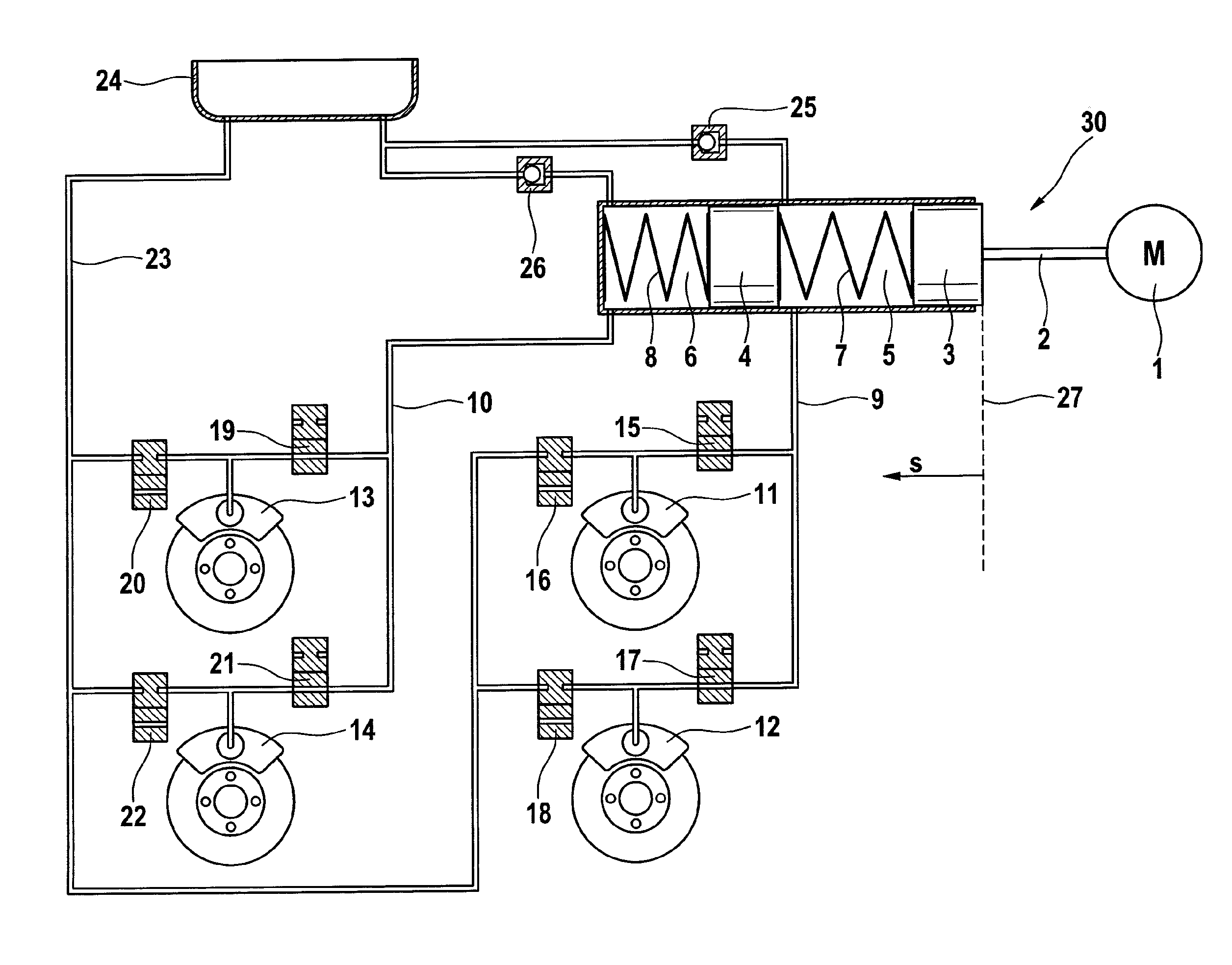
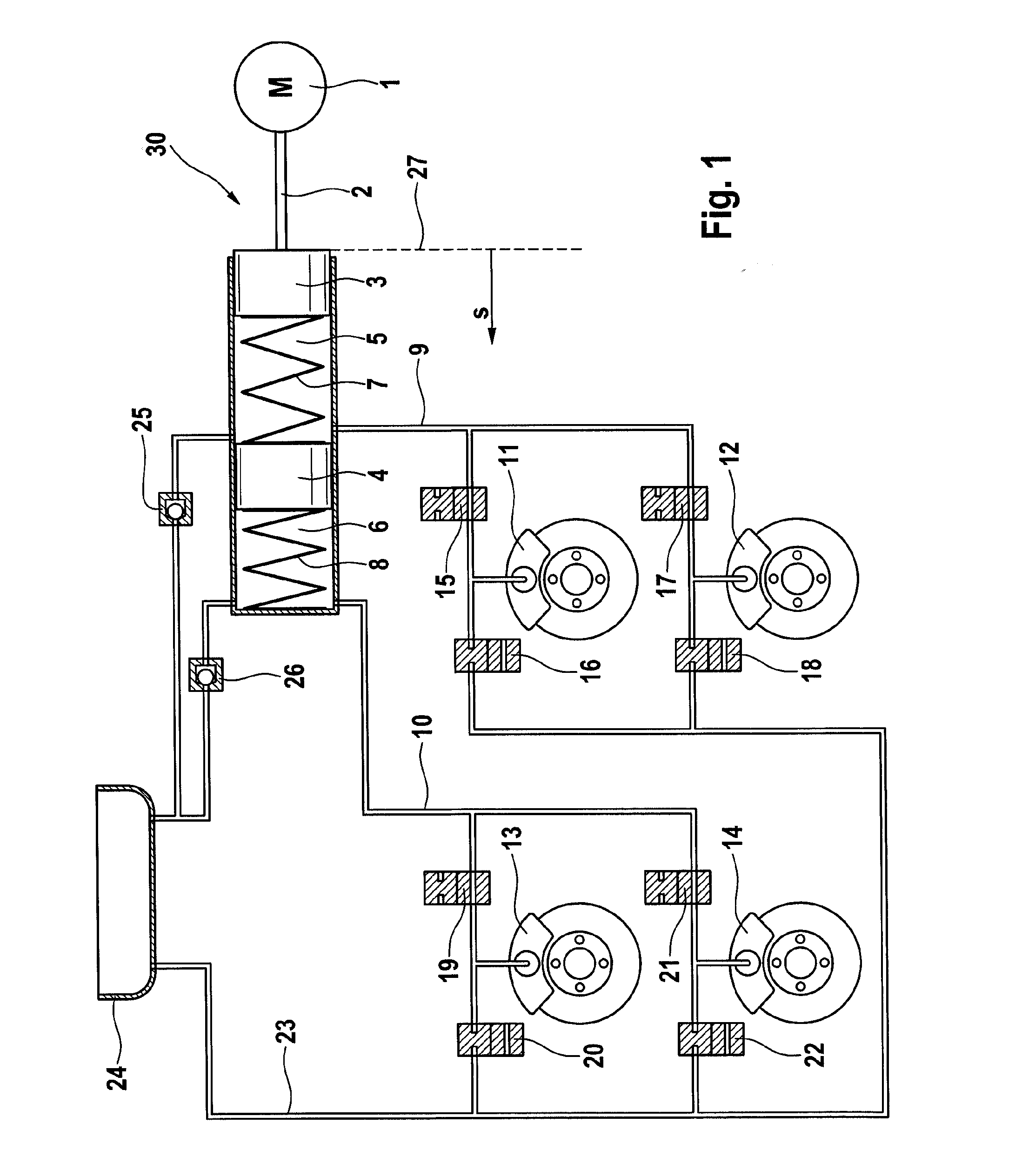
[0030]FIG. 1 illustrates the simplified principle of an active electrohydraulic braking system having in accordance with the example, four antilock braking controllable wheel brakes, which is suitable for performing a method in accordance with the invention. In the case of the braking system, the driver submits, e.g. by means of a brake pedal movement, a braking pressure request PRequest—Driver that is implemented electronically with the aid of a pressure generating device 30. The pressure generating device 30 comprises in accordance with the example an electric motor 1, suitable gearing 2 and a cylinder-piston arrangement that comprises a piston 3, a floating piston 4 and two hydraulic pressure chambers 5 and 6. The piston 3 can be displaced in the cylinder by means of the electric motor that is embodied in a manner such that it can reverse. Two wheel brakes 11, 12, 13, 14 are connected to each of the two pressure chambers 5, 6 by means of in each case an electrically controllable,...


PUM


Abstract

A method and system for controlling an electrohydraulic braking system for a motor vehicle having an antilock braking control function and an electrically controllable pressure generating device having a cylinder-piston arrangement having a hydraulic pressure chamber and a piston displaceable by an electromechanical actuator so that a predetermined pressure can be set in the chamber, and having a number of hydraulically wheel brakes connected to the hydraulic pressure chamber by an electrically actuatable inlet valve and to a pressure medium reservoir by means of an electrically actuatable outlet valve. The cylinder-piston arrangement is actuated in case of antilock controlling at all wheel brake for setting an individual wheel target pressure at each wheel brake, such that the pressure in the hydraulic pressure chamber is set to the greatest wheel target pressure.

Description

CROSS REFERENCE TO RELATED APPLICATIONS[0001]This application claims priority to German Patent Application Nos. 10201003825.2, filed Jul. 23, 2010, 102011077329.0, filed Jun. 10, 2011, and PCT / EP2011 / 061929, filed Jul. 13, 2011.FIELD OF THE INVENTION[0002]The invention relates to a method for controlling an electrohydraulic braking system for motor vehicles in and an electrohydraulic braking system.BACKGROUND AND SUMMARY OF THE INVENTION[0003]“Brake-by-wire” braking systems are being used ever more frequently in automotive technology. Braking systems of this type frequently comprise in addition to a master brake cylinder that can be actuated by the vehicle driver, an electrically controllable pressure generating device by means of which in the operating mode “brake-by-wire” the wheel brakes or the master brake cylinder are actuated. In order to provide the vehicle driver with a pleasant pedal sensation in the “brake-by-wire” operating mode, the braking systems generally comprise a b...

Claims


Application Information

Patent Timeline
IPC IPC(8): B60T8/176
CPCB60T8/176B60T8/326B60T8/3655B60T8/4054B60T8/4072B60T13/745B60T8/32B60T8/40B60T13/74
Inventor ROLL, GEORGBOHM, JURGENJAGER, JENS
Owner CONTINENTAL TEVES AG & CO OHG
Why Eureka
Try Eureka