Monitoring of floating roof tank

a technology for monitoring and floating roofs, applied in the direction of reradiation, containers, transmission systems, etc., can solve the problems of limited monitoring of floating roofs, part of floating roofs could get stuck to the inner wall of tanks, and the environment on top of floating roofs is a hazardous or potentially hazardous environment, so as to minimize any system maintenance, minimize any system down time, and maximize the life of monitoring systems

Active Publication Date: 2013-05-16
ROSEMOUNT TANK RADAR
View PDF14 Cites 41 Cited by
  • Summary
  • Abstract
  • Description
  • Claims
  • Application Information

AI Technical Summary

Benefits of technology

[0014]In hazardous or potentially hazardous environment monitoring of floating roofs, in addition to enabling efficient installation and providing a safe and reliable monitoring function, it is of utmost importance according to the inventor to maximize life of the monitoring system, minimize any system maintenance, and minimize any system down time. An unnecessary complexity of the monitoring system should also be avoided.
[0022]The interchangeability of the energy storage units is enhanced according to the invention by said power supply circuitry connection interface having power supply circuitry electro-mechanical contact terminals and said energy storage unit connection interface having energy storage unit electro-mechanical contact terminals. In operation, respective ones of these terminals are kept in conductive electric contact with each other across the interfaces of the power supply circuitry and the energy storage units, respectively. This is achieved by releasable pressure means, such as a threaded cover lid, fastening screws, a latch mechanism or similar, in order to provide ease of interchangeability of said energy storage unit.
[0033]The presently most preferred gauging technology is continuous guided wave radar level gauging, since it will provide the benefits of continuous level measurement and a long life of the energy storage units, since it can be made to consume very little power.

Problems solved by technology

In case of fuel and oil tanks, the environment on top of the floating roof is a hazardous or potentially hazardous environment.
Consequently, it is also important that any interruption of the monitoring of the floating roof is limited.
In filling of the tank, part of the floating roof could get stuck to the inner wall of the tank.
As the filling proceeds the floating roof will be partially flooded by liquid, with a potentially hazardous situation as a result, should gas or vapor so produced be explosive or otherwise harmful.
The roof structure braking could lead to an even more severe result.
In discharging of the tank, part of the floating roof could get stuck to the inner wall of the tank.
In the subsequent event of a roof collapse, an explosive atmosphere could form above the oil and the collapsed roof.
This increase in friction could increase the risk of a roof getting stuck.
This could cause the roof to sink or tilt and collapse.
Also liquid leakage into the float means (pontoons) of the floating roof may cause a roof to partially sink and become flooded with liquid.
It is believed that any existing or previously described monitoring systems for floating roofs have either been too complicated or otherwise lacked in ease of applicability in hazardous or potentially hazardous environments of floating roof tanks and thus have not been used in any large extent.

Method used


Image

  • Monitoring of floating roof tank
  • Monitoring of floating roof tank
  • Monitoring of floating roof tank

Examples


Embodiment Construction

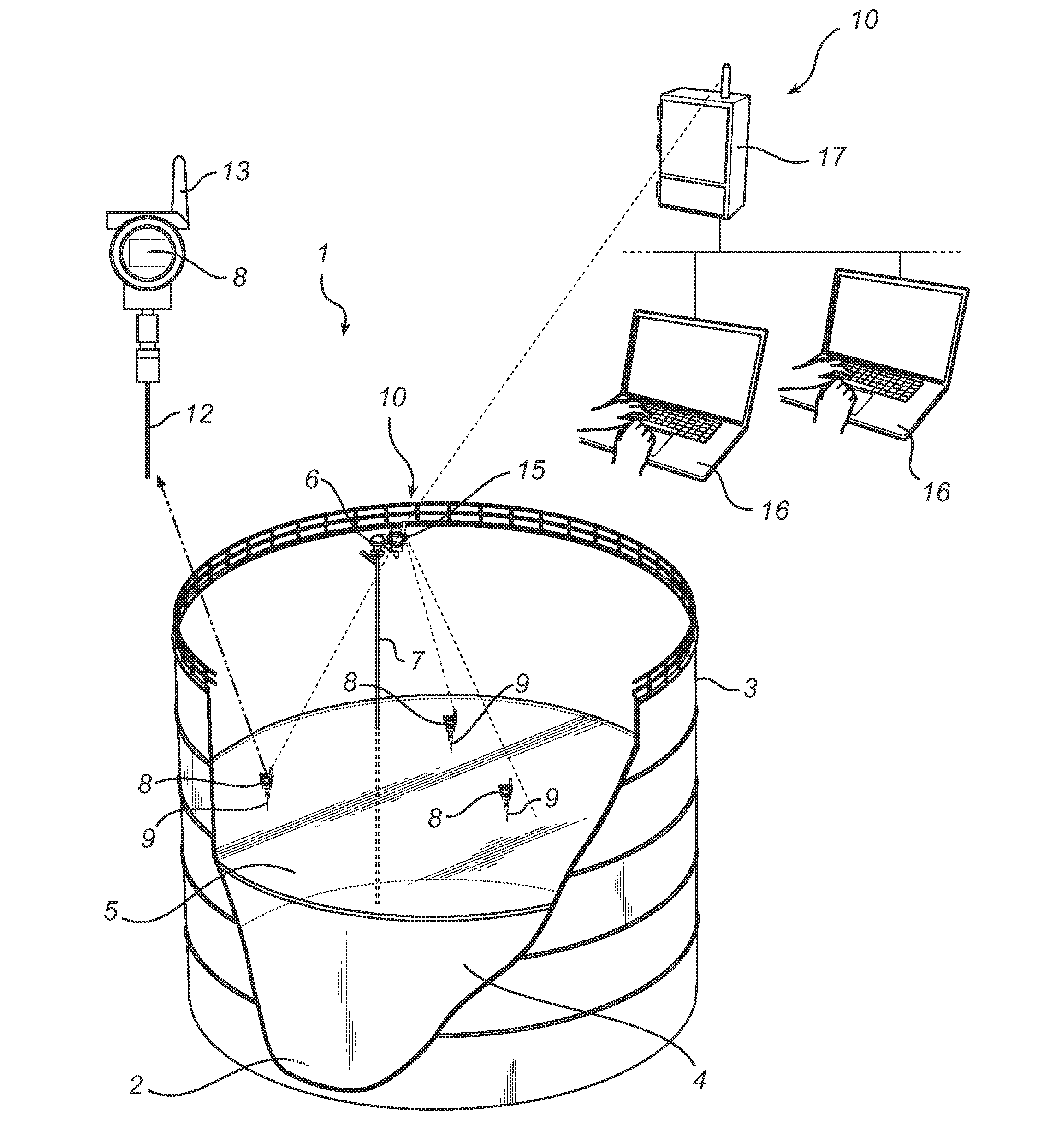
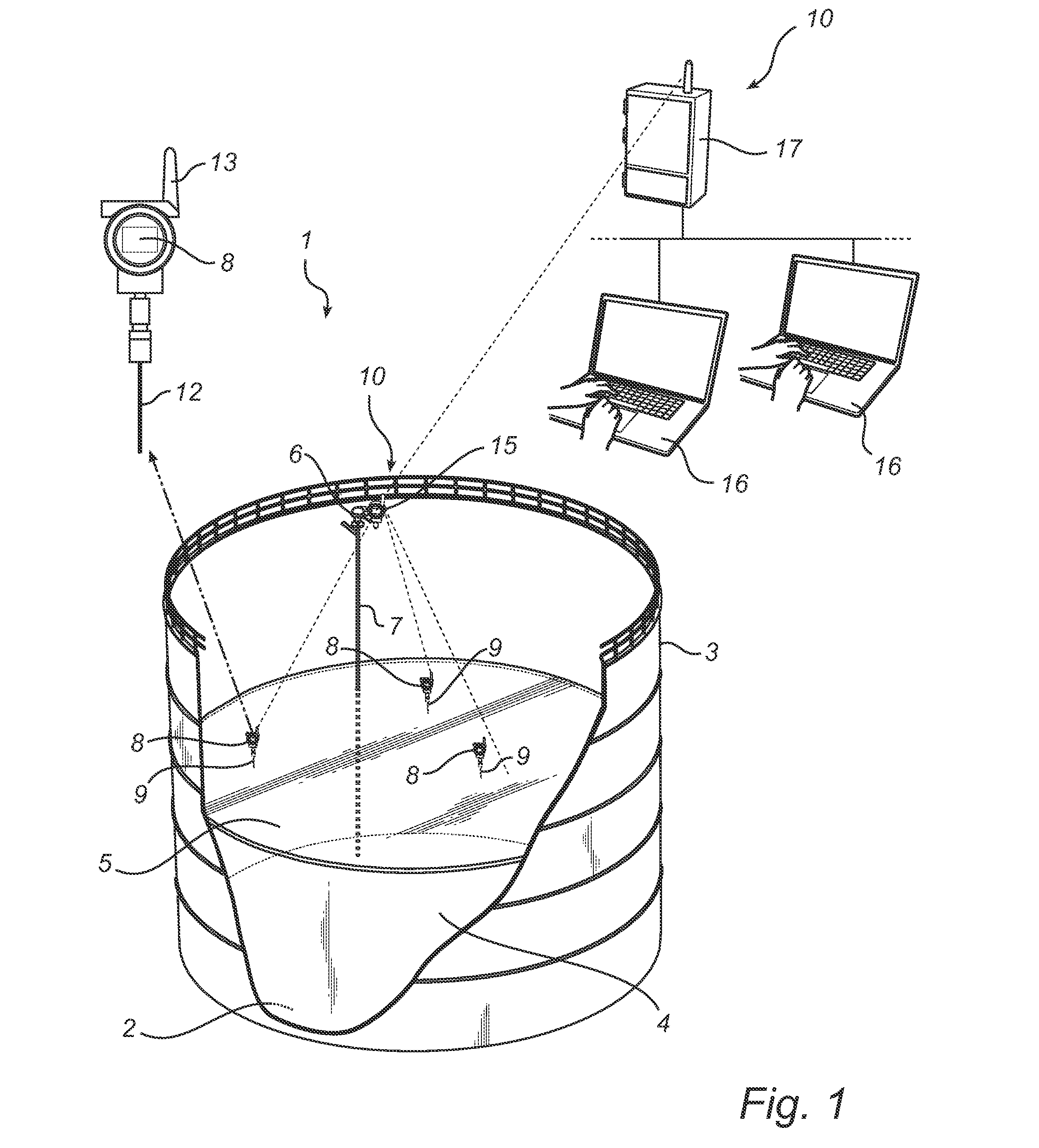
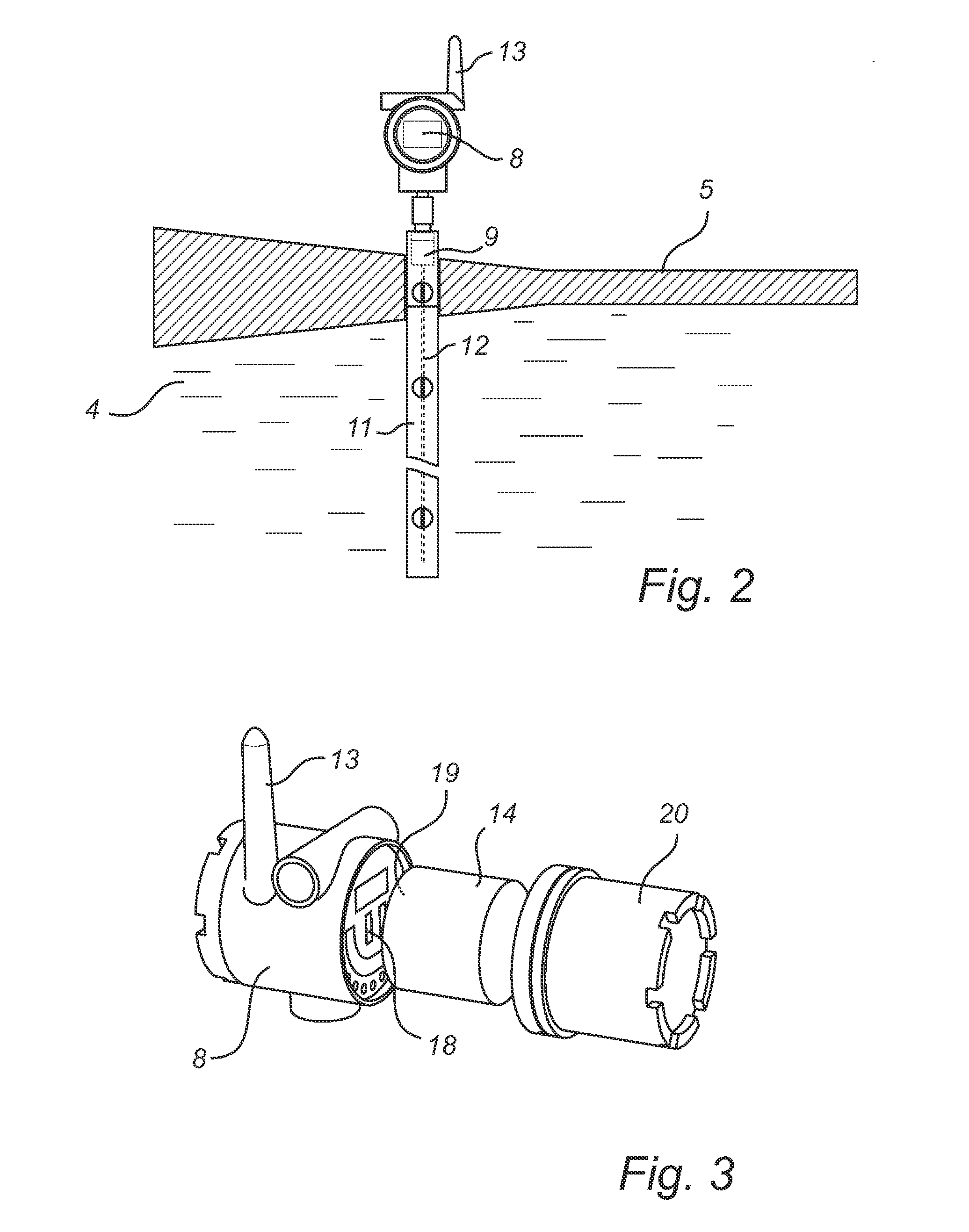
[0037]With reference to FIGS. 1 through 3, embodiments of the invention is applied to a large floating roof tank 1 having a bottom 2 and a side wall 3. The tank 1 is made of steel and has a diameter of several tens of meters. The tank contains liquid oil 4 or a petroleum product on top of which a floating roof 5 floats by means of floats (not shown) integrated with the floating roof 5. The floating roof 5 has a seal (not shown) along its perimeter for limiting the passage of liquid and gas between the floating roof 5 and an inside of the side wall 3. As the skilled person will appreciate, the floating roof tank 1 and its associated equipment may further include pipes attachments, pipes, valves, actuators for filling and discharging the oil, and various measuring and control devices et cetera. In particular, the tank 1 is equipped with a oil level gauge 6 that measures a filling level of the oil 4 relative to a reference point of the tank 1 and, more specifically, often a datum plate...


PUM


Abstract

System for monitoring a floating roof of a tank containing a liquid, wherein the system determines a local status of the floating roof in spaced apart sensing element locations. In a hazardous or potentially hazardous environment, there is an on-roof subsystem including a sensing element in each sensing element location, intrinsically safe measuring circuitry coupled a sensing elements and arranged for determining said local status, intrinsically safe radio communication on-roof circuitry coupled for communicating externally of the on-roof subsystem the local, an intrinsically safe power supply circuitry connected to an intrinsically safe and interchangeable energy storage unit for powering the on-roof subsystem. The system further includes monitoring circuitry for receiving the indication of local status and for determining an overall monitored status of said floating and further radio communication circuitry. The on-roof subsystem is wireless in its power supply and communication.

Description

FIELD OF THE INVENTION[0001]The present invention relates to a monitoring system for monitoring a floating roof of a floating roof tank and to a monitoring method for monitoring a floating roof of a floating roof tank. The invention further relates to a method of re-powering a monitoring system for monitoring a floating roof of a floating roof tank.BACKGROUND OF THE INVENTION[0002]In large liquid tanks, in particular fuel and oil tanks at refineries and the like, which are capable of holding large amounts of oil products, use is frequently made of a floating roof which floats on the liquid in the tank and is therefore displaceable in a vertical direction. Thus, the floating roof is capable of following the level of a liquid (oil product) when the liquid is discharged from or filled into the tank. Floating roofs of this type are used for preventing leakage of vapors and gases from the tank into the atmosphere and ingress of e.g. rainwater from the surroundings into the liquid. Typica...

Claims


Application Information

Patent Timeline
Patent Type & Authority Applications(United States)
IPC IPC(8): G08C19/16
CPCG01F23/00G01F23/0069G01F23/284H04Q9/00B65D88/34B65D90/48G01S7/003G01S13/87G01S13/88B65D2590/0083H04Q2209/40H04Q2209/823H04Q2209/88H01Q1/2233G01F23/802
Inventor HAGG, LENNART
Owner ROSEMOUNT TANK RADAR
Why Eureka
Try Eureka