Three dimensional scanning beam system and method

a scanning beam and three-dimensional technology, applied in the field of scanning beam systems, can solve the problems of errors introduced to the rigidly mounted scanning beam system, the inability of conventional navigation systems to operate or be practical, and the inability to meet the needs of the market, and achieve the effect of convenient commercial choi

Active Publication Date: 2013-05-16
COMMONWEALTH SCI & IND RES ORG
View PDF4 Cites 16 Cited by
  • Summary
  • Abstract
  • Description
  • Claims
  • Application Information

AI Technical Summary

Benefits of technology

[0007]It is an object of some embodiments of the present invention to provide consumers with improvements and advantages over the above described prior art, and / or overcome and alleviate one or more of the above described disadvantages of the prior art, and / or provide a useful commercial choice.

Problems solved by technology

Mapping and localization, including simultaneous localisation and mapping (SLAM), are fundamental problems in mobile robotics, and include scenarios in which a moving object with no known map or accurate measure of its pose must estimate and maintain both.
In particular, it is well known that in some environments conventional navigation systems cannot operate or are not practical.
For example, in environments such as inside buildings, in underground mines, or in deep water, satellite-based global positioning system (GPS) technologies and cellular-based positioning technologies are often inoperative.
However, in some circumstances errors can be introduced to a rigidly mounted scanning beam system due to vibrations or jouncing of a vehicle or robot to which the system is attached.
Therefore complex vibration isolation and stabilisation systems have been devised to effectively isolate 3D scanning beam systems from unwanted vibrations or movement.
In some applications the required hardware necessary to increase the field of view of a scanning sensor to effectively scan a three dimensional region can be prohibitively complex and expensive.

Method used


Image

  • Three dimensional scanning beam system and method
  • Three dimensional scanning beam system and method
  • Three dimensional scanning beam system and method

Examples


Embodiment Construction

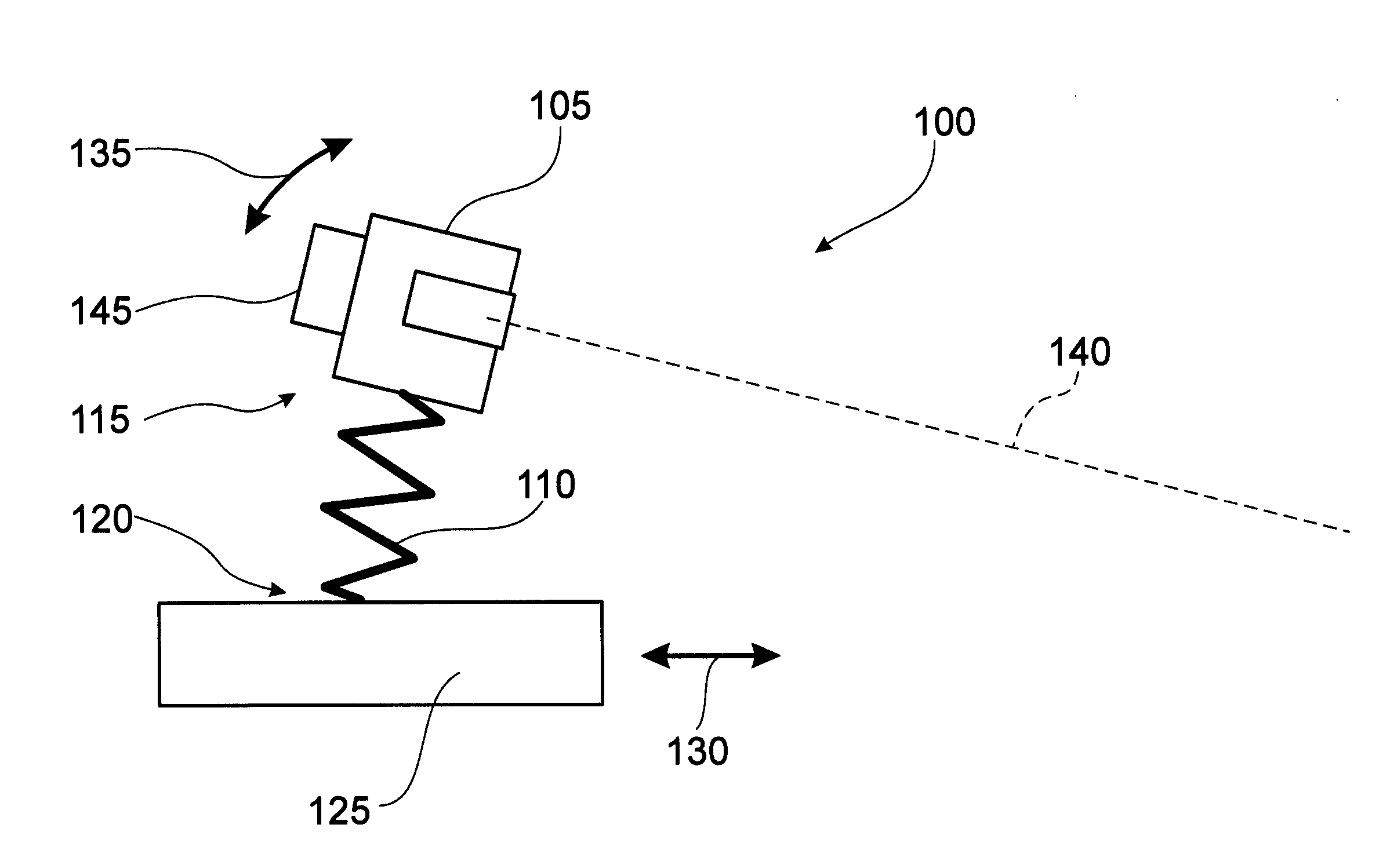
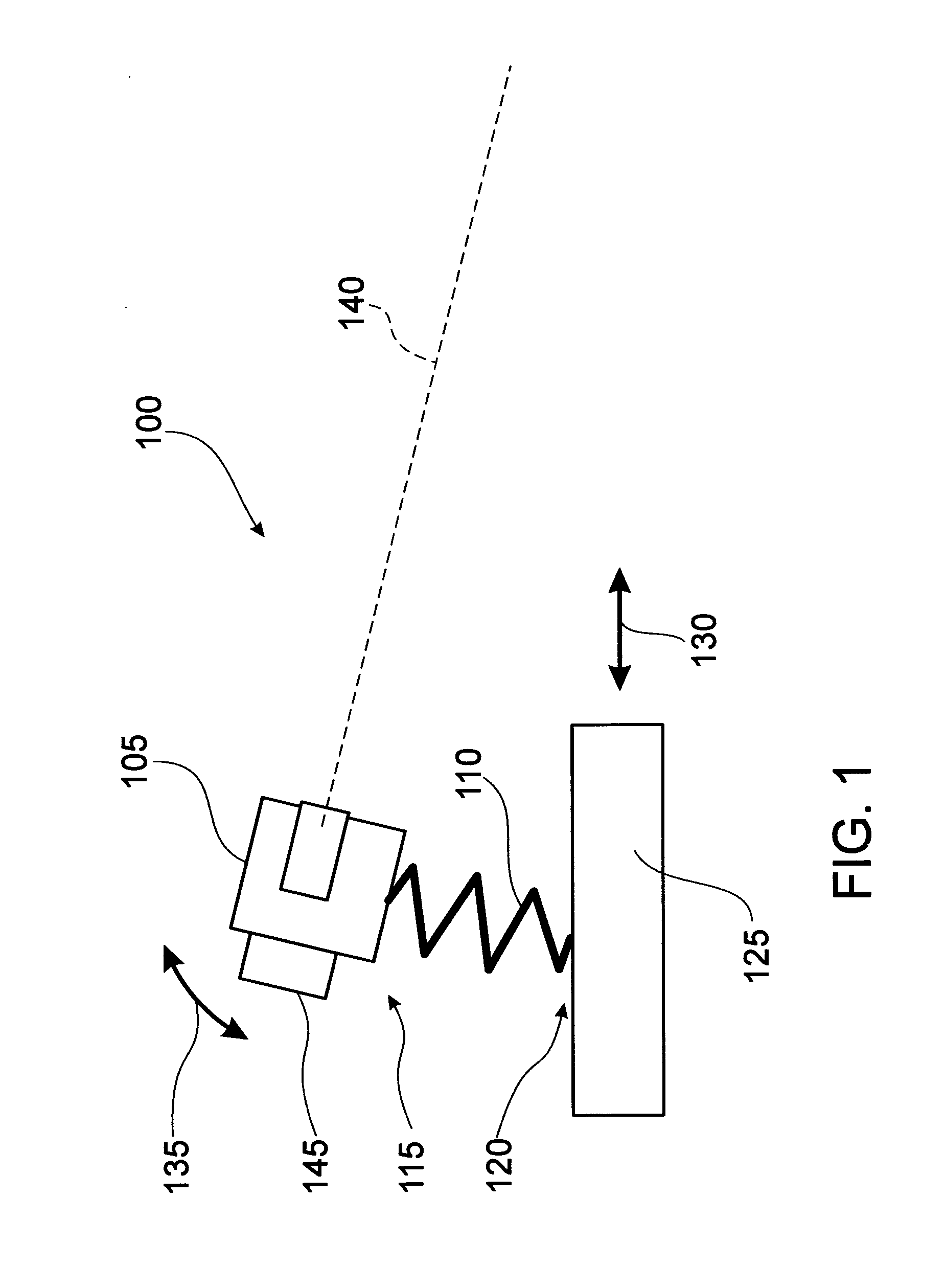
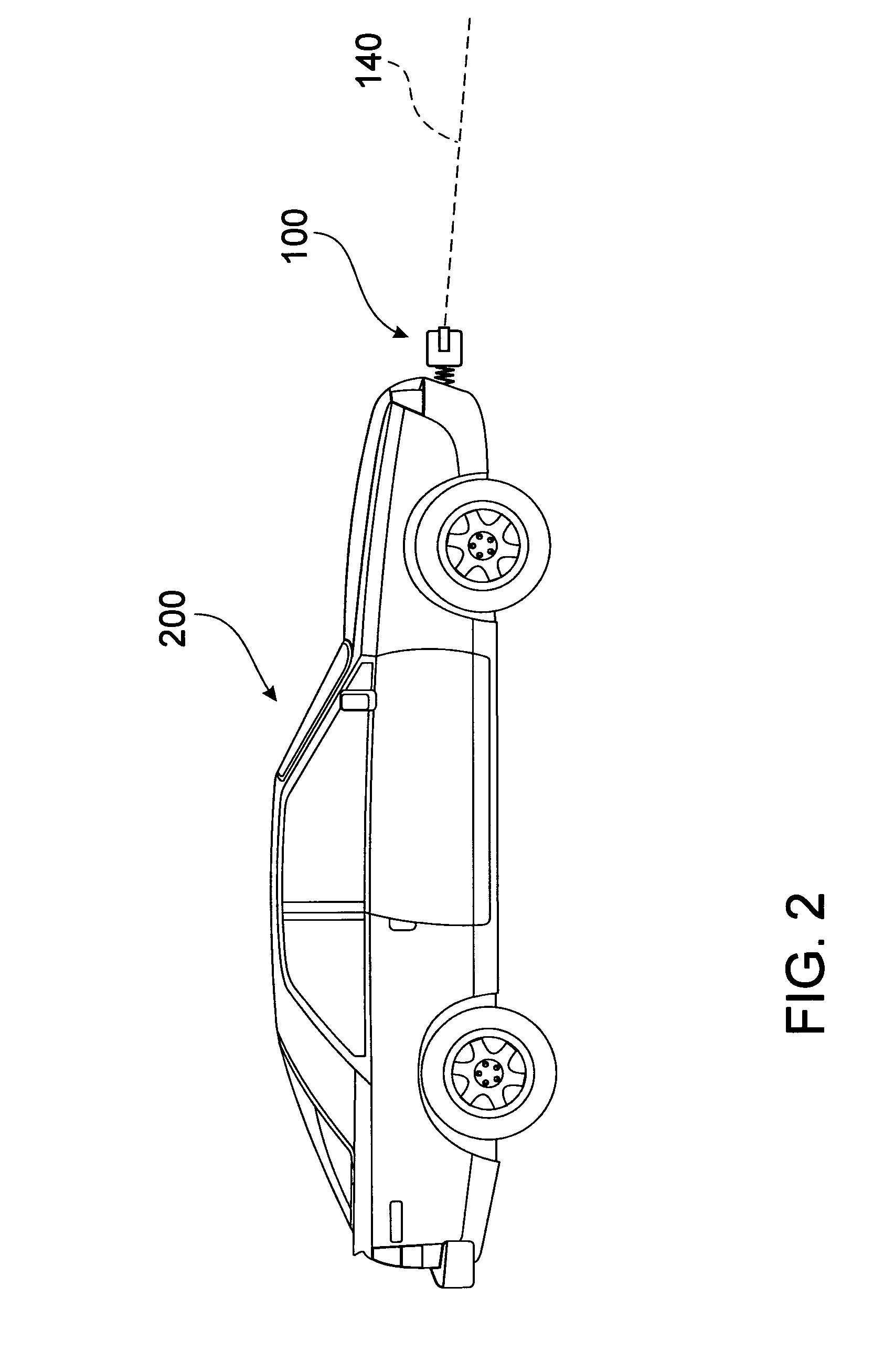
[0038]The present invention relates to a 3D scanning beam system and method. By attaching the system to an object, such as a vehicle, robot, person or animal, 3D scans of an environment can be obtained economically and reliably. Data from the 3D scans then can be used for various purposes such as object detection, proximity detection, mapping, localization, or collision avoidance.

[0039]In this patent specification, adjectives such as first and second, left and right, top and bottom, etc., are used solely to define one element or method step from another element or method step without necessarily requiring a specific relative position or sequence that is described by the adjectives. Words such as “comprises” or “includes” are not used to define an exclusive set of elements or method steps. Rather, such words merely define a minimum set of elements or method steps included in a particular embodiment of the present invention.

[0040]Referring to FIG. 1, a schematic diagram illustrates a ...


PUM


Abstract

A three dimensional scanning beam system (100) and method (500) enable economical and efficient three dimensional scans of an environment. The system (100) includes a ranging apparatus (105), and a reactive linkage mechanism (110) having a first end (115) and a second end (120). The first end (115) is connected to the ranging apparatus (105) and the second end (120) is connected to an object (125) that moves the system (100) through an environment. In use acceleration of the object (125) with respect to the environment is converted by the reactive linkage mechanism (110) to motion of the ranging apparatus (105) with respect to the object (125), which increases the field of view of the ranging apparatus (105) with respect to the environment.

Description

FIELD OF THE INVENTION[0001]The present invention relates generally to scanning beam systems. In particular, although not exclusively, the invention relates to a system and method for three dimensional (3D) scanning using a reactive linkage mechanism.BACKGROUND OF THE INVENTION[0002]Vehicles, people or robots that operate in environments where no a priori map is available often must construct a map in order to function and adapt to their working environment, or to provide accurate models for an end user. Mapping and localization, including simultaneous localisation and mapping (SLAM), are fundamental problems in mobile robotics, and include scenarios in which a moving object with no known map or accurate measure of its pose must estimate and maintain both.[0003]The pose of an object refers to its position and orientation in space. Accurate knowledge of the pose of moving objects is often important for mobile tasks such as robot navigation, mapping, and planning. In particular, it is...

Claims


Application Information

Patent Timeline
Patent Type & Authority Applications(United States)
IPC IPC(8): G01S17/08G01S15/08G01S13/08G01S17/89G01S17/931
CPCG01S17/08G01S13/08G01S15/08G01S7/4817G01S17/89G01S17/936G01S17/42G01S17/931
Inventor BOSSE, MICHAELZLOT, ROBERT
Owner COMMONWEALTH SCI & IND RES ORG
Why Eureka
Try Eureka