
Planar ion funnel

a funnel and ion technology, applied in the field of ion control, can solve the problems of reducing the efficiency of ion transmission, so as to achieve compact instrument configuration, more compact instrument, and more compact

Inactive Publication Date: 2013-05-16
SRI INTERNATIONAL
View PDF10 Cites 27 Cited by
  • Summary
  • Abstract
  • Description
  • Claims
  • Application Information

AI Technical Summary

Benefits of technology

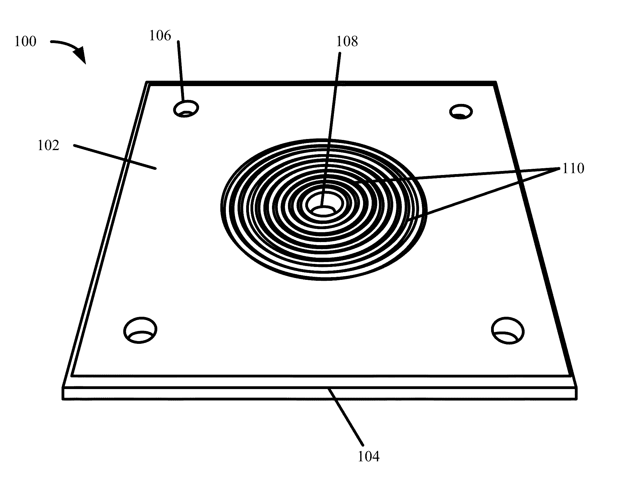
The patent describes a new design for a device used to control ions in a low pressure environment. The device is made up of a planar substrate, conductive layer, and an orifice for receiving ions. A structure is formed in the conductive layer to generate an electric field and connectors for supplying power. This design is more compact than traditional devices and can be manufactured using MEMs-related processes. The device can be powered with DC power, which is more efficient and simplifies electronics. The device can be operated in a low pressure environment with a pressure of less than 40 Torr. The technical effects of this design include more compact size, ease of manufacturing, and efficient operation.

Problems solved by technology

At elevated pressures (e.g., about 1 Torr and above), collisions with gas molecules increasingly dominate the behavior of ion motion and it becomes much more challenging to control ion motion over larger areas or volumes.
For example, the high rate of collisions inhibits effective focusing of ions with static lens stack.
However, the use of a skimmer causes only a small fraction of the ion cloud to be sampled, which reduces the efficiency of the ion transmission and creates a major sensitivity bottleneck for mass spectrometry.
However, there are some mass spectrometry applications where a traditional ion funnel configuration is not optimal.

Method used


Image

  • Planar ion funnel
  • Planar ion funnel
  • Planar ion funnel

Examples


Embodiment Construction

[0026]In the following paper, numerous specific details are set forth to provide a thorough understanding of the concepts underlying the described embodiments. It will be apparent, however, to one skilled in the art that the described embodiments may be practiced without some or all of these specific details. In other instances, well known process steps have not been described in detail in order to avoid unnecessarily obscuring the underlying concepts.

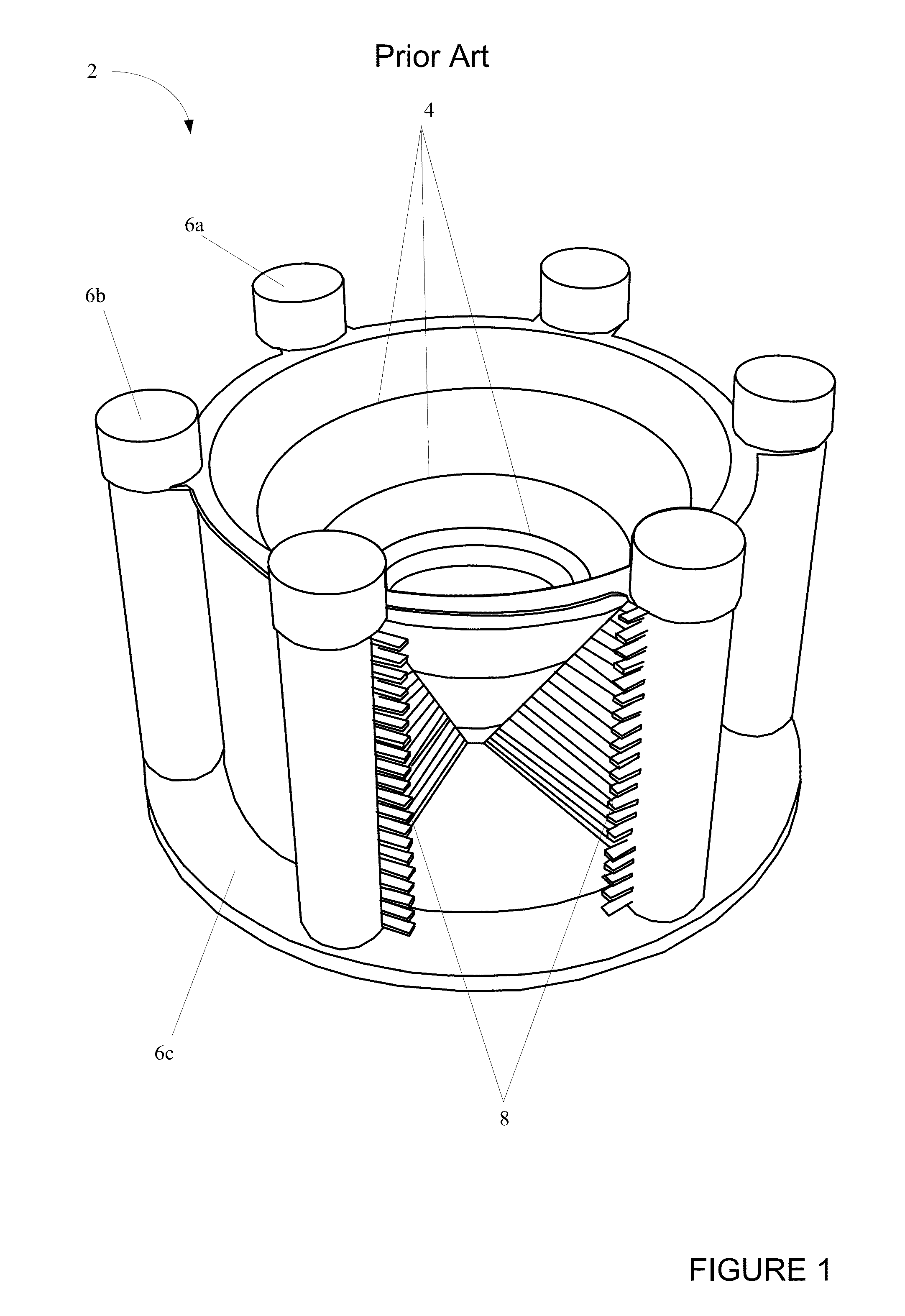
[0027]Traditional ion funnels have been primarily developed to improve the sensitivity of mass spectrometers. In the mass spectrometer, an ion funnel receives ions from an ion source where components of a sample to be analyzed are ionized. The entrance and the exit to the ion funnel are typically circular where the area of the entrance is larger than the exit. Between the entrance and exit, the funnel includes a number of circular rings of a decreasing area. When joined, the circular rings provide a 3-D conical shape. Out-of-phase RF p...


PUM


Abstract

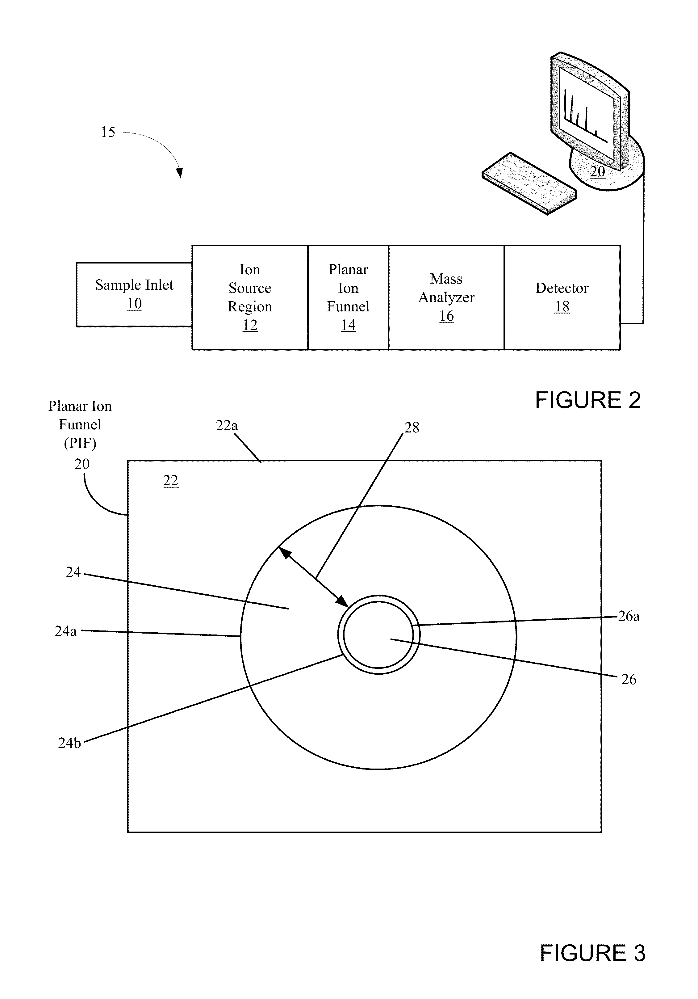
A planar ion funnel is disclosed that can be used for ion control. In one application, the planar ion funnel can be used for ion control in a mass spectrometer. The planar ion funnel can be formed on a surface of a substantially planar substrate including an orifice. An electrically conductive structure can be formed on a top surface of the substrate that surrounds the orifice. In operation, a power can be applied to the conductive structure that causes an electric field to be generated that draws ions into and through the orifice. In one embodiment, the orifice can be circular and the conductive structure can be a series of nested rings of increasing diameter surrounding the orifice.

Description

CROSS REFERENCE TO RELATED APPLICATIONS[0001]This patent application claims priority under 35 U.S.C. §119(e) to U.S. Provisional Patent Application Ser. No. 61 / 560,657 entitled, “Planar Ion Funnel,” filed Nov. 16, 2011, which is incorporated by reference in its entirety for all purposes.FIELD OF THE INVENTION[0002]The present invention is generally related to ion control in a low pressure environment. More particularly, the present invention is directed to providing an ion funnel for manipulating and focusing ions for applications such as mass spectrometry.BACKGROUND OF THE INVENTION[0003]In recent years, mass spectrometry has become an important analysis tool in the physical and biological sciences. Mass spectrometry is an analytical technique that is used primarily to determine masses of particles, an elemental composition of a sample or the chemical structure of a molecule. Mass spectrometry works by creating ions from a sample to generate charged atoms, molecules or molecule fra...

Claims


Application Information

Patent Timeline
IPC IPC(8): H01T23/00
CPCH01J49/066H01T23/00
Inventor VAN AMEROM, FRISO H.W.CHAUDHARY, ASHISHSHORT, R. TIMOTHY
Owner SRI INTERNATIONAL
Learn More