Apparatus and Method of Reporting Power Headroom in Wireless Communication System

Inactive Publication Date: 2013-05-16
LG ELECTRONICS INC
View PDF13 Cites 81 Cited by
  • Summary
  • Abstract
  • Description
  • Claims
  • Application Information

AI Technical Summary

Benefits of technology

[0012]A base station can recognize whether a user equipment arbitrarily regulates the transmit power, and can more accurately know about available tr

Problems solved by technology

If the transmit power is too low, the BS may not be able to correctly receive the data.
If the transmit power is too high, it may cause interfe

Method used


Image

  • Apparatus and Method of Reporting Power Headroom in Wireless Communication System
  • Apparatus and Method of Reporting Power Headroom in Wireless Communication System
  • Apparatus and Method of Reporting Power Headroom in Wireless Communication System

Examples


Embodiment Construction

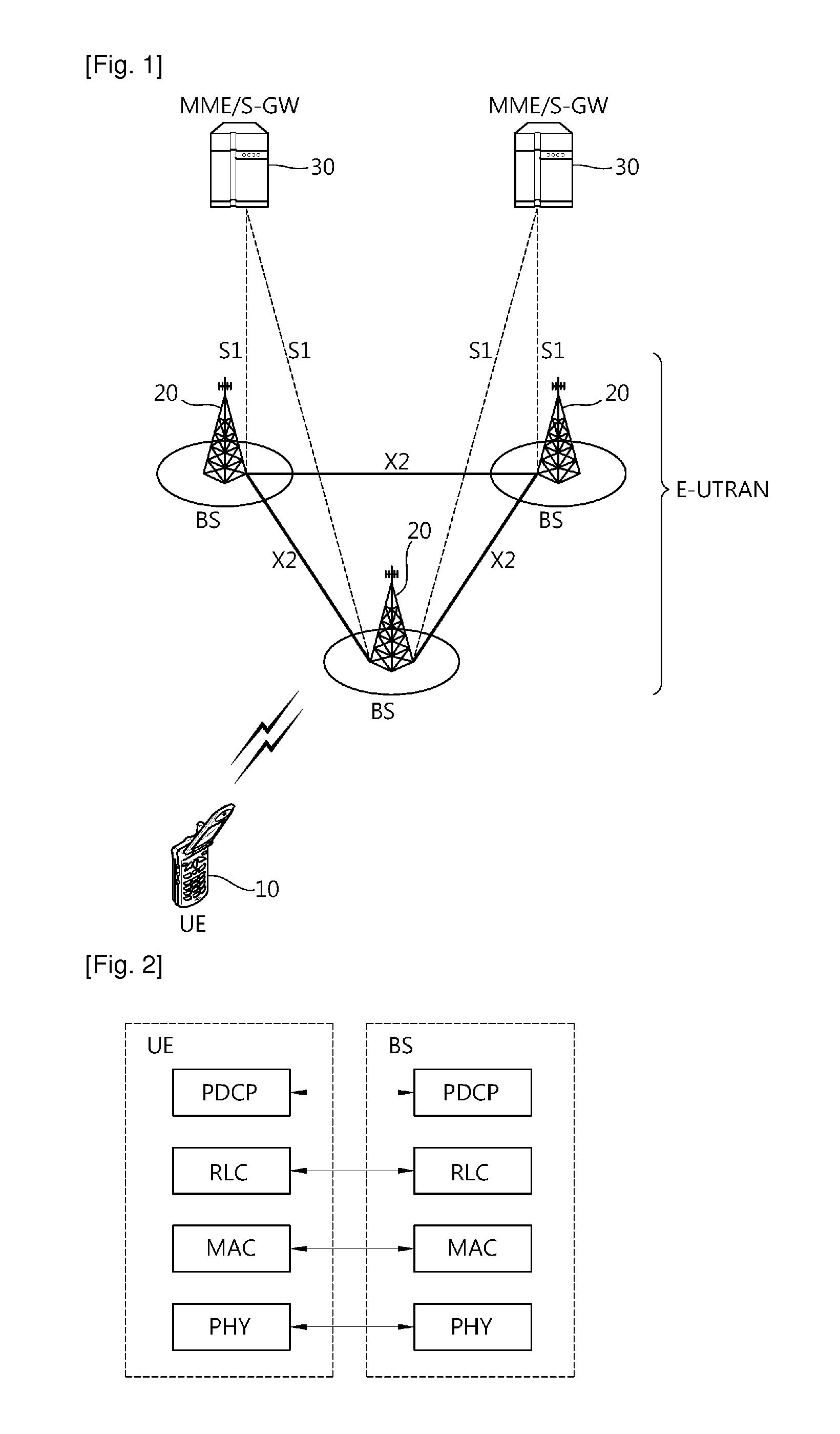
[0023]FIG. 1 shows a wireless communication system to which the present invention is applied. A wireless communication system may also be referred to as an evolved-UMTS terrestrial radio access network (E-UTRAN) or a long term evolution (LTE) / LTE-A system.

[0024]The E-UTRAN includes at least one base station (BS) 20 which provides a control plane and a user plane to a user equipment (UE) 10. The UE 10 may be fixed or mobile, and may be referred to as another terminology, such as a mobile station (MS), a user terminal (UT), a subscriber station (SS), a mobile terminal (MT), a wireless device, etc. The BS 20 is generally a fixed station that communicates with the UE 10 and may be referred to as another terminology, such as an evolved node-B (eNB), a base transceiver system (BTS), an access point, etc.

[0025]The BSs 20 are interconnected by means of an X2 interface. The BSs 20 are also connected by means of an S1 interface to an evolved packet core (EPC) 30, more specifically, to a mobil...


PUM


Abstract

A method and apparatus of reporting a power headroom in a wireless communication system is provided. A user equipment determines a power headroom based on a configured transmit power and transmits a power headroom report to a base station. The power headroom report includes a power headroom level indicating the power headroom and a backoff indicator indicating whether the user equipment applies power backoff due to power management.

Description

TECHNICAL FIELD [0001]The present invention relates to wireless communications, and more particularly, to a method and apparatus of reporting a power headroom in a wireless communication system.BACKGROUND ART [0002]3rd generation partnership project (3GPP) long term evolution (LTE) is an improved version of a universal mobile telecommunication system (UMTS) and is introduced as the 3GPP release 8. The 3GPP LTE uses orthogonal frequency division multiple access (OFDMA) in a downlink, and uses single carrier-frequency division multiple access (SC-FDMA) in an uplink. The 3GPP LTE employs multiple input multiple output (MIMO) having up to four antennas. In recent years, there is an ongoing discussion on 3GPP LTE-advanced (LTE-A) that is an evolution of the 3GPP LTE.[0003]It is important to properly regulate transmit power when a user equipment (UE) transmits data to a base station (BS). If the transmit power is too low, the BS may not be able to correctly receive the data. If the transm...

Claims


Application Information

Patent Timeline
IPC IPC(8): H04W52/30
CPCH04W52/30H04W52/365
Inventor JUNG, SUNG HOONCHUN, SUNG DUCKYI, SEUNG JUNELEE, YOUNG DAEPARK, SUNG JUN
Owner LG ELECTRONICS INC
Why Eureka
Try Eureka