Cutting method for glass sheet and glass sheet cutting apparatus

a cutting apparatus and glass sheet technology, applied in manufacturing tools, transportation and packaging, cellulosic plastic layered products, etc., can solve the problems of glass sheet breaking from cracks, factor of deterioration in the product quality of glass sheet, etc., to reduce risk, suppress force, and safe separation

Active Publication Date: 2013-05-16
NIPPON ELECTRIC GLASS CO LTD
View PDF7 Cites 73 Cited by
  • Summary
  • Abstract
  • Description
  • Claims
  • Application Information

AI Technical Summary

Benefits of technology

[0090]According to the first invention as described above, the gap between the fused end surfaces of the thin flat glass is strictly managed based on the relationship relative to the thickness of the thin flat glass. As a result, the shape of the vicinity of each of the fused end surfaces of the thin flat glass can be satisfactorily maintained. Further, the fused thin flat glasses can be safely separated without bringing the fused end surfaces into contact with each other.
[0091]According to the second invention as described above, it is possible to suppress the force by which the vicinity of the cutting portion in the molten state is pressed downward by the jetted gas. Thus, the glass sheet can be cut by fusing without defectively shaping the cut end surface of the product portion of the glass sheet.
[0092]According to the third invention as described above, the assist gases are jetted from both above and below to the cutting portion of the glass sheet, and the molten foreign matter blown off by the assist gases is captured by being sucked above and below the glass sheet. Thus, it is possible to reliably reduce a risk that the molten foreign matter adheres to the product portion of the glass sheet, and to satisfactorily maintain cleanliness of the product portion.
[0093]According to the fourth invention as described above, during the laser fusing of the glass sheet, the operational efficiency at the time of cutting the glass sheet is improved, and the product quality of the cut surfaces of the glass sheet after cutting is enhanced.

Problems solved by technology

However, in the above-mentioned cutting method using the bending stress, cracks are liable to be formed in cut surfaces, which may lead to a problem that the glass sheet is broken from the cracks.
In this case, the melts scattered by the center assist gas may become a foreign matter called dross and adhere to a glass sheet, which constitutes a factor of deterioration in product quality of the glass sheet.

Method used


Image

  • Cutting method for glass sheet and glass sheet cutting apparatus
  • Cutting method for glass sheet and glass sheet cutting apparatus
  • Cutting method for glass sheet and glass sheet cutting apparatus

Examples


embodiments of first invention

[0113]In the following, description is made of the above-mentioned embodiment of the first invention with reference to the drawings. Note that, in the following, a glass sheet refers to a glass substrate for flat panel displays, which has a thickness 500 μm or less. As a matter of course, the glass sheet to be cut is not limited to the glass substrate for flat panel displays, and may be glass substrates utilized in various fields, such as a glass substrate for solar cell, OLED illumination devices, touch panels, and digital signages, and laminated bodies formed of such glass substrates and organic resins.

first embodiment

(1) First Embodiment

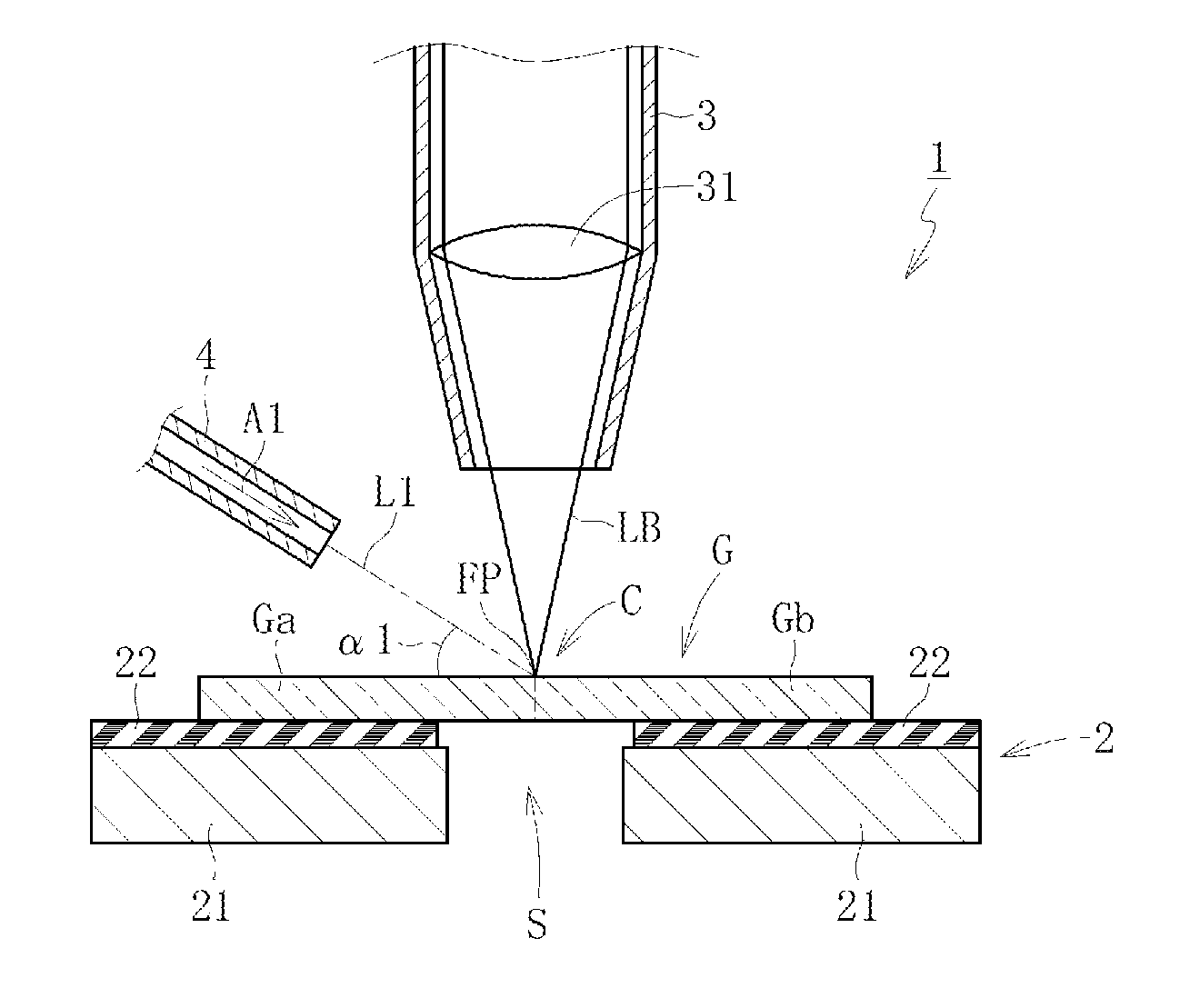
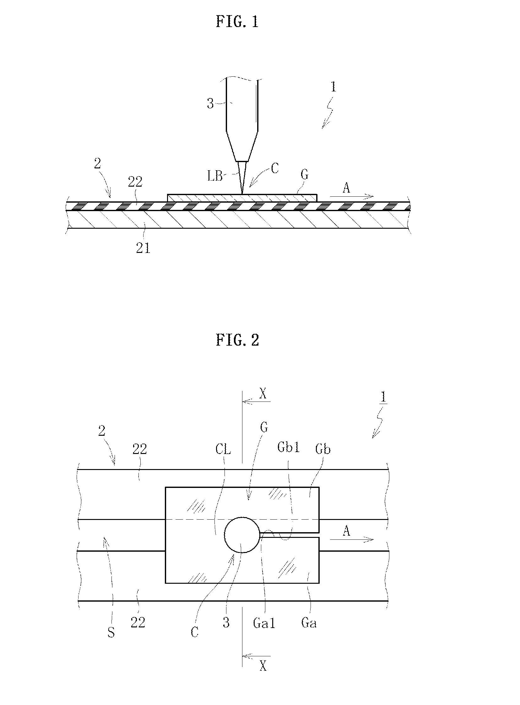
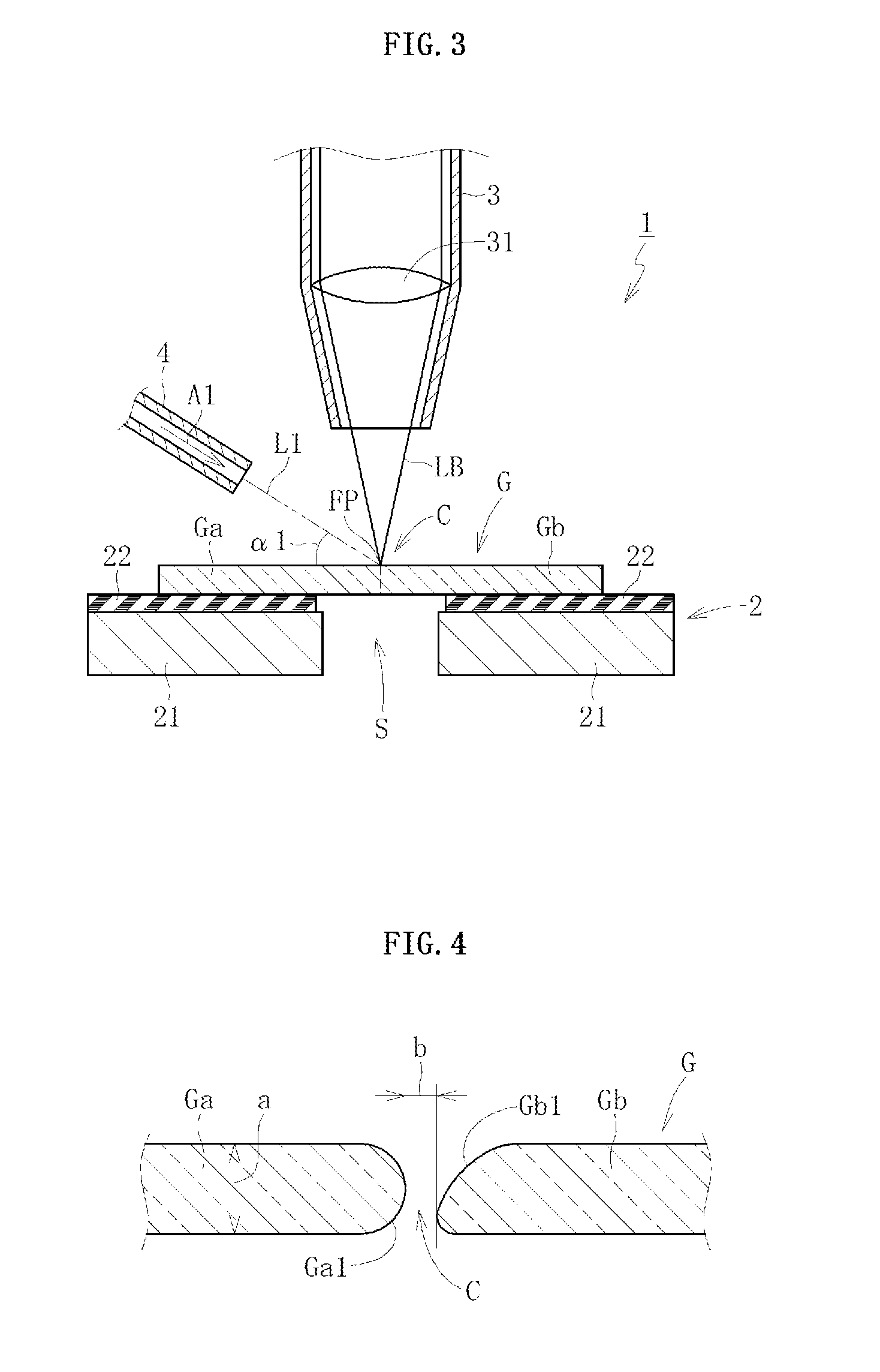
[0114]As illustrated in FIG. 1, a glass sheet cutting device 1 according to a first embodiment of the first invention comprises a support stage 2 for supporting from below a glass sheet G in a flat posture and a laser irradiator 3 for fusing and dividing the glass sheet G supported by the support stage 2.

[0115]The support stage 2 comprises a stage main body 21 and a conveyer 22 which moves along an upper surface of the stage main body 21. The glass sheet G is conveyed downstream in a conveying direction (arrow A direction in FIG. 1) along a preset cutting line CL by movement of the conveyer 22. In this case, the stage main body 21 functions to guide the conveyer 22. Note that, the conveyer 22 comprises a large number of vents (not shown), and the glass sheet G is conveyed while being held on the conveyer 22 by attraction through intermediation of those vents. As a matter of course, there may be employed other conveying methods such as a method of conveying the gl...

second embodiment

(2) Second Embodiment

[0143]As illustrated in FIG. 5, the glass sheet cutting device 1 according to a second embodiment of the first invention is obtained by adding a center assist gas jet nozzle 5 to the structure of the glass sheet cutting device 1 according to the first embodiment. In the following, description is made only of differences while omitting description of common features.

[0144]The center assist gas jet nozzle 5 is connected to a distal end portion of the laser irradiator 3, and supplies a center assist gas A2 into the interior space of the laser irradiator 3 (space below the lens 31). The center assist gas A2 supplied into the interior space of the laser irradiator 3 is jetted just below from a distal end of the laser irradiator 3 to the cutting portion C of the glass sheet G. In other words, from the distal end of the laser irradiator 3, the laser beam LB is emitted and the center assist gas A2 is jetted. The center assist gas A2 has functions to remove the molten fo...


PUM

PropertyMeasurementUnit
thicknessaaaaaaaaaa
roughnessaaaaaaaaaa
arithmetic mean roughnessaaaaaaaaaa

Abstract

Provided is a cutting method for a glass sheet, comprising radiating a laser beam to a cutting portion (C) of a glass sheet (G) having a thickness of 500 μm or less to fuse the glass sheet (G), wherein a narrowest gap between fused end surfaces (Ga1 and Gb1) of the glass sheet (G), which face each other in the cutting portion (C), is managed to satisfy a relationship of 0.1≦b/a≦2, where “a” is a thickness of the glass sheet (G) and “b” is the narrowest gap.

Description

TECHNICAL FIELD[0001]The present invention relates to an improvement of a cutting technology for fusing glass sheets.BACKGROUND ART[0002]Conventionally, as a cutting method for glass sheets, there has been widely used a method of cleaving a glass sheet by applying a bending stress to a scribe line formed with a diamond cutter or the like on a surface of the glass sheet (cleaving using a bending stress).[0003]However, in the above-mentioned cutting method using the bending stress, cracks are liable to be formed in cut surfaces, which may lead to a problem that the glass sheet is broken from the cracks. As a countermeasure, instead of the above-mentioned cutting method using the bending stress, in some cases, there has been employed laser fusing for cutting a cutting portion of the glass sheet by melting the cutting portion by using irradiation heat generated by radiating a laser beam to the cutting portion of the glass sheet.[0004]As a cutting method for a glass sheet using the laser...

Claims


Application Information

Patent Timeline
Patent Type & Authority Applications(United States)
IPC IPC(8): C03B33/02
CPCC03B33/0222C03B33/082Y10T428/24777B23K26/1452B23K26/38B23K26/1405B23K26/142B23K26/1438B23K2103/50B23K2103/54Y02P40/57B23K26/402
Inventor FUJII, TAKAHIDEUCHIDA, SETSUOINAYAMA, NAOTOSHINODA, TAKAYUKIITOH, SHOETA, MICHIHARU
Owner NIPPON ELECTRIC GLASS CO LTD
Why Eureka
Try Eureka