
Tracking system for healthcare facilities

Inactive Publication Date: 2013-05-16
PRECISION DYNAMICS CORPORATION
View PDF5 Cites 47 Cited by
  • Summary
  • Abstract
  • Description
  • Claims
  • Application Information

AI Technical Summary

Benefits of technology

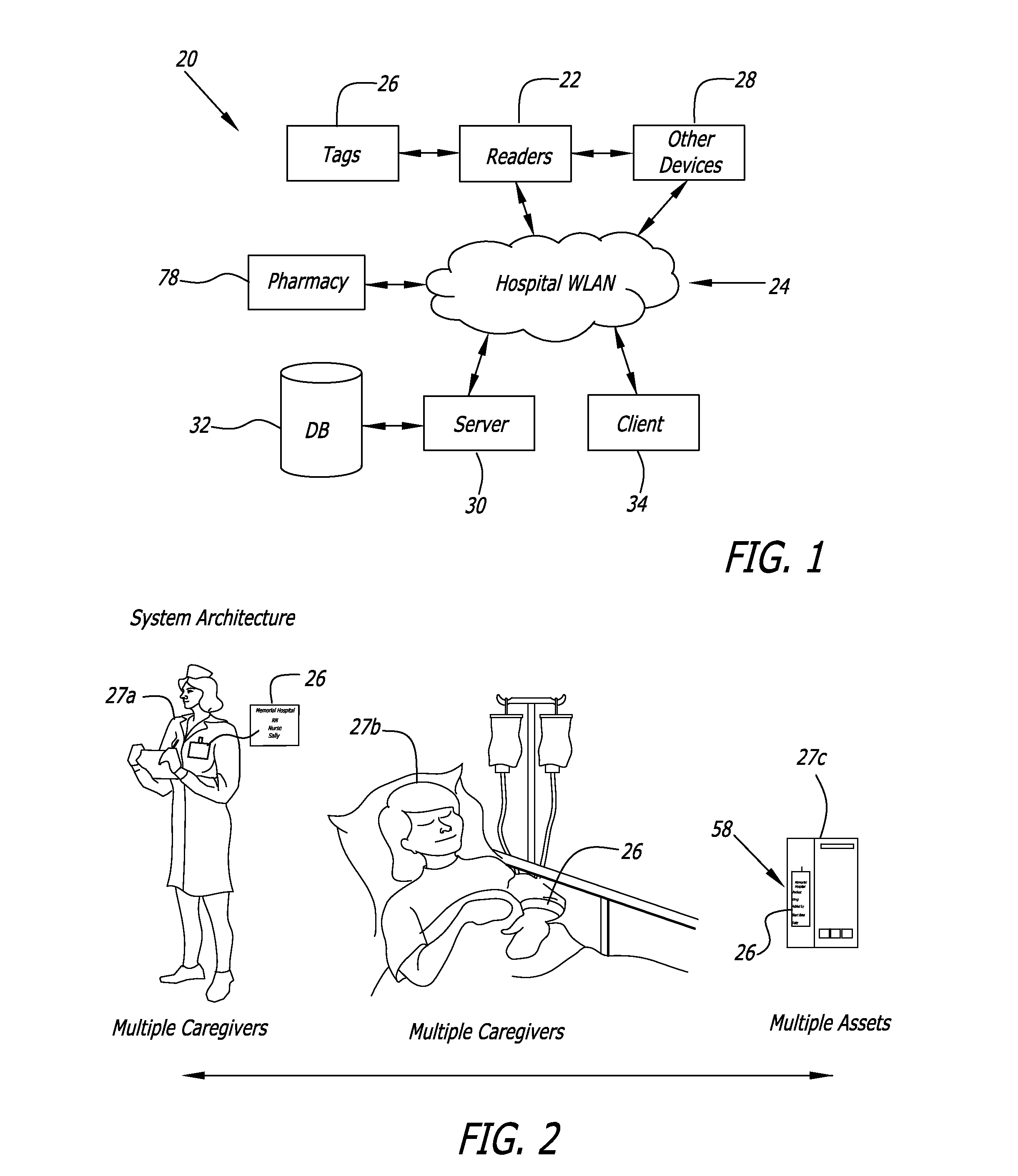
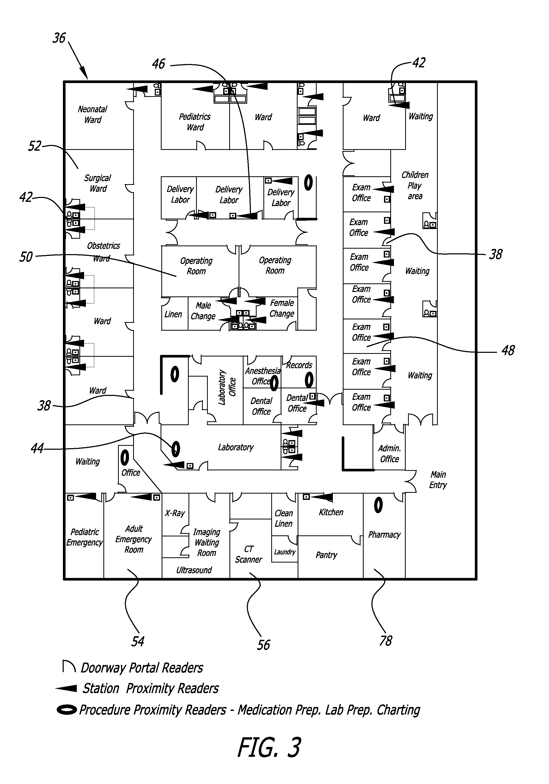
The present invention is a system for tracking interactions between patients, caregivers, equipment, and other entities in a patient care environment. It aims to reduce cost and complexity relative to existing RTLS-only systems, by focusing data collection upon discrete interactions. The system includes a computer system and a database coupled to a network. It stores and executes software modules including a data capture module, an IS plan tracking module, and an analytics and dashboard module. By recognizing when patients, clinicians, or equipment enters or leaves a room and coupling that with information on when clinicians or equipment is in close proximity to a patient, a sufficient amount of needed location information is available. The system uses simpler and less expensive techniques, such as portal type readers and bed mounted proximity readers, to provide this level of data.

Problems solved by technology

In practice however, RTLS systems have been found to be expensive to implement and prone to technical challenges.
The resulting systems are expensive and very difficult to maintain.
Accomplishing this granularity of tracking is technically challenging and expensive both to implement and maintain.

Method used


Image

  • Tracking system for healthcare facilities
  • Tracking system for healthcare facilities
  • Tracking system for healthcare facilities

Examples


embodiment 1

Schedule II Pain Medication Delivery (FIG. 8)

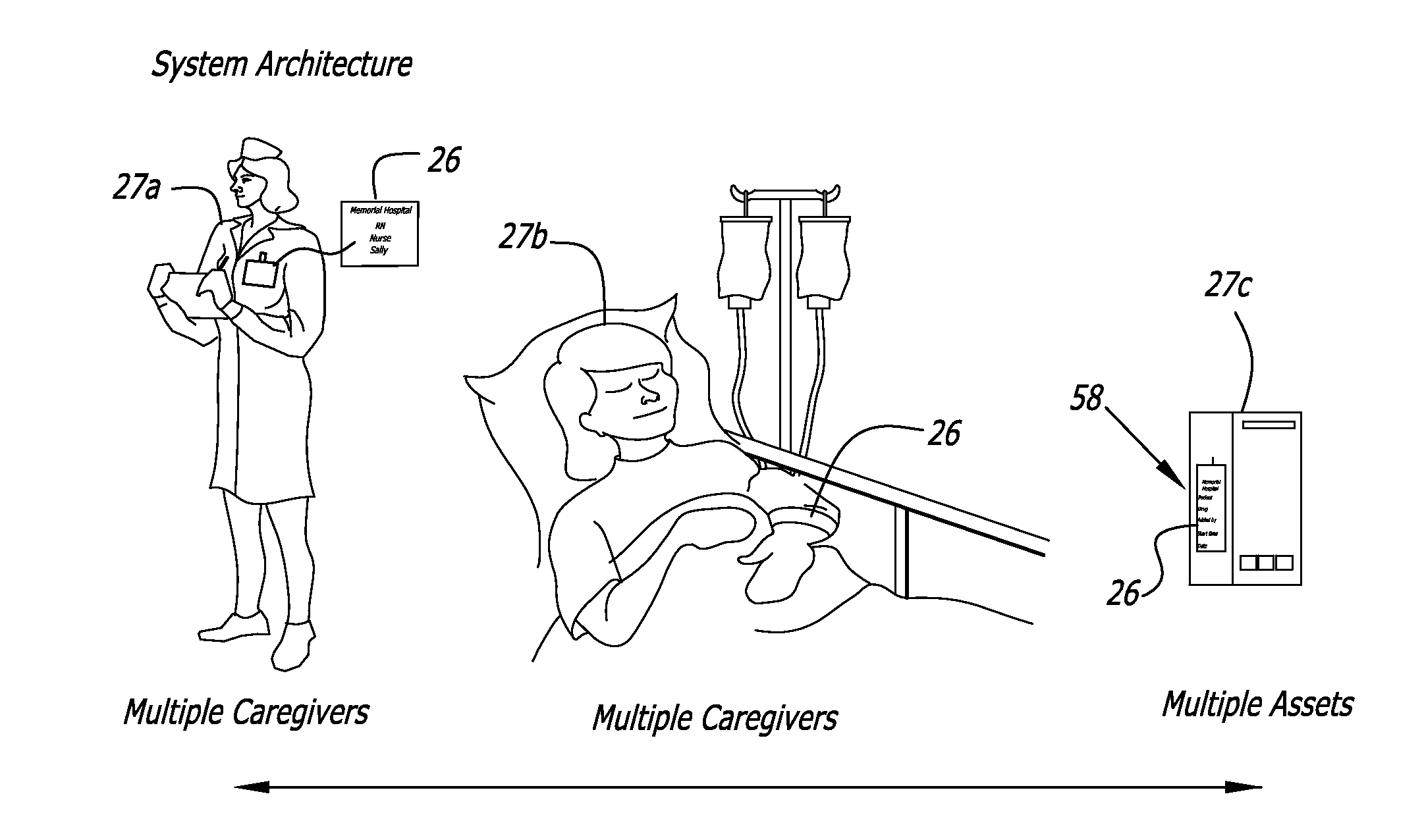
[0089]An example of an IS plan 72 according to step 202 is a request for a caregiver 27a to inject a schedule II pain medication into the IV (intravenous) line of a patient 27b. The IS plan 72 is to be carried out within a twenty minute window, the expected time period, to be on time. Based on this IS plan 72 module 200 would define twenty minutes from the start of the IS plan 72 as bounding the expected time period and, for example, one hour to bound the maximum time period.

[0090]According to step 204, software module 200 would identify or receive a reader ID 62 corresponding to the hospital bed 40 of the patient 27b, a tag ID 64 corresponding to the administering caregiver 27a, and optionally a tag ID 64 corresponding to a witnessing caregiver 27a.

[0091]According to step 206 software module 200 would define the following expected sequence of interactions: (1) Pyxis® station or pharmacy 78 to have medication available, (2) administering...

embodiment 2

Procedure Requiring Equipment Delivery (FIG. 8)

[0094]According to step 202, an IS plan 72 is received for a caregiver 27a to perform a procedure on a patient 27b requiring the delivery of equipment 27c. The patient 27b is also contagious. The procedure is not extremely urgent and will be performed within the expected time period or twenty-four hours as the equipment 27c may be available. According to this example, the expected time period is twenty-four hours and a maximum time period selected to be three days. The maximum time period corresponds to the maximum time that the interaction sequence would be expected to take based upon historical records.

[0095]According to step 204 the IS plan 72 would define an expected sequence of interactions that identify a reader ID 62 corresponding to a glove and robe station 46, a reader ID 62 corresponding to a patient bed 40, a tag ID 64 corresponding to a patient 27b, a tag ID 64 corresponding to a caregiver 27a, and a tag ID 64 corresponding ...

embodiment 3

A Change in Indication or Diagnosis for a Patient: Patient is Contagious and Less Stable

[0099]In this third example an existing IS plan 72 is replaced with a new IS plan 72 based upon a change in the diagnosis and / or condition of the patient 27b. In this example the patient 27b that was stable and not contagious is now unstable and contagious. According to step 202 a new IS plan 72 replaces and supersedes an existing IS plan 72 having an addition of new equipment 27c, i.e., cardiac monitoring, new medications (heart rhythm medication), new temporal expectations (defined time periods between visits is reduced), and other requirements (glove and robe). This example is different than the prior two because there are actually two different interaction sequences—one for each of two caregivers 27a. The expected sequence time for the sequences is ten minutes or minimum and the maximum sequence time is thirty minutes because this is a borderline emergency.

[0100]According to step 204 assets a...


PUM


Abstract

A location / tracking system for use in hospitals and similar healthcare facilities is based upon a “last seen” location for patients, clinicians, or high value equipment. The system uses portal readers to determine when and where an item to be tracked passes through a portal, bed or exam chair mounted proximity reader to determine when and how long an item is proximate to a reader in order to determine when and for how long the item is proximate to a particular task area. Real time tracking and retrospective analysis of transaction data enables locating an item to be tracked and allows higher level analysis of the transaction data to determine metrics for “time to test”, “time to treatment”, and similar statistics.

Description

BACKGROUND OF THE INVENTION[0001]The present invention concerns a low cost system and method for tracking interactions between assets in a patient care environment. In this disclosure, “assets” means: (1) persons or entities, such as patients, caregivers, visitors, etc.; (2) rooms or stations, such as exam rooms, operating rooms, ICU, recovery, etc.; and (3) equipment or objects, such as, hand wash dispensers, testing or diagnostic machines, washing stations, etc. More particularly the present invention concerns a system that computes patient care environment effectiveness metrics by comparing a sequence of interaction records to a sequence of expected interactions in which each interaction record documents an interaction between two or more entities (e.g., caregivers, patients, and equipment) in the patient care environment.[0002]Real Time Location Systems (RTLS) have become popular in hospitals as a way to reduce costs and improve efficiency through real time access to information...

Claims


Application Information

Patent Timeline
IPC IPC(8): G06Q50/24G16H10/60G16H40/67
CPCG06Q10/08G06Q50/28G06Q50/22G06Q10/06G16H40/20G16H40/67
Inventor ELLIS, RICK
Owner PRECISION DYNAMICS CORPORATION
Learn More