FLOW CONDITIONER FOR FUEL INJECTOR FOR COMBUSTOR AND METHOD FOR LOW-NOx COMBUSTOR

a fuel injector and flow conditioner technology, applied in the direction of engine starters, engine/propulsion engine ignition, lighting and heating apparatus, etc., can solve the problem of generally emitting unacceptable levels of nosub>x

Inactive Publication Date: 2013-05-23
SOLAR TURBINES
View PDF5 Cites 14 Cited by
  • Summary
  • Abstract
  • Description
  • Claims
  • Application Information

AI Technical Summary

Benefits of technology

[0007]The disclosure describes, in one aspect, an injector for a gas turbine combustor. The injector includes an inner wall, at least one catalyst coated surface disposed within the inner wall and forming at least one passage adapted to provide a feed gas flow through the injector, and at least one channel disposed within the inner wall and adapted for passage of an oxidant gas flow through the injector. At least one of the feed gas flow or the oxidant gas flow establishes an axial gas flow through the inner wall and to the combustor. The injector further includes a flow conditioner disposed within the axial gas flow. The flow conditioner includes an elongated body having a length, an upstream end, a downstream end, an exterior surface at least partially disposed within the inner wall, and an interior passage for passage of the axial gas flow. The interior passage extends along the length of the flow conditioner, opening into the upstream and downstream ends and including an interior diameter. The interior diameter of the flow conditioner substantially smoothly reduces and then increases from the upstream end to the downstream end.

Problems solved by technology

Flames in non-premixed combustion, that is, the combustion process wherein fuel and oxidizer (typically air) mix and burn concurrently, generally emit unacceptable levels of NOx, for example, over 200 parts-per-million (ppm), substantially higher than regulations allow for certain applications.

Method used


Image

  • FLOW CONDITIONER FOR FUEL INJECTOR FOR COMBUSTOR AND METHOD FOR LOW-NOx COMBUSTOR
  • FLOW CONDITIONER FOR FUEL INJECTOR FOR COMBUSTOR AND METHOD FOR LOW-NOx COMBUSTOR
  • FLOW CONDITIONER FOR FUEL INJECTOR FOR COMBUSTOR AND METHOD FOR LOW-NOx COMBUSTOR

Examples


Embodiment Construction

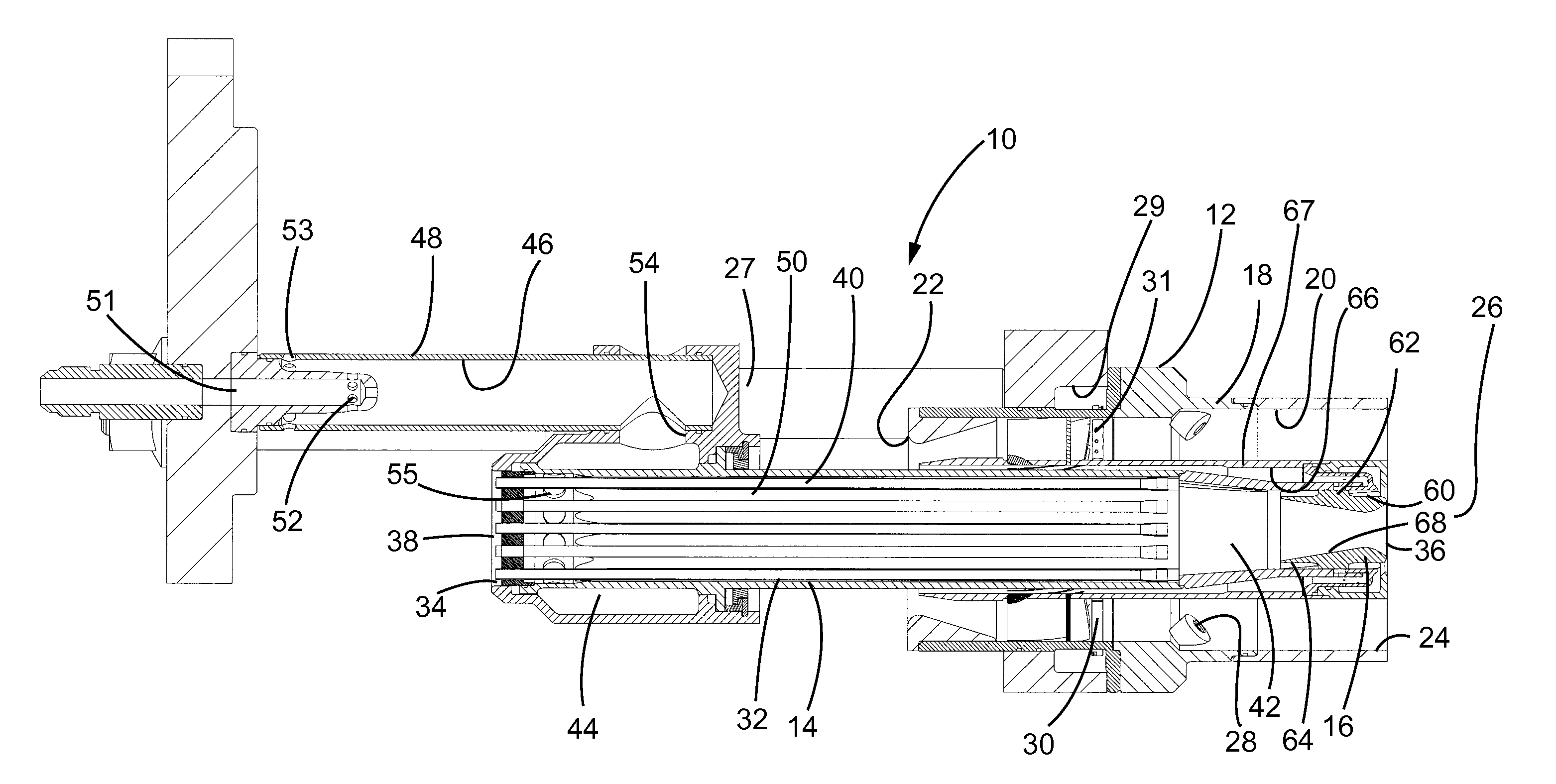
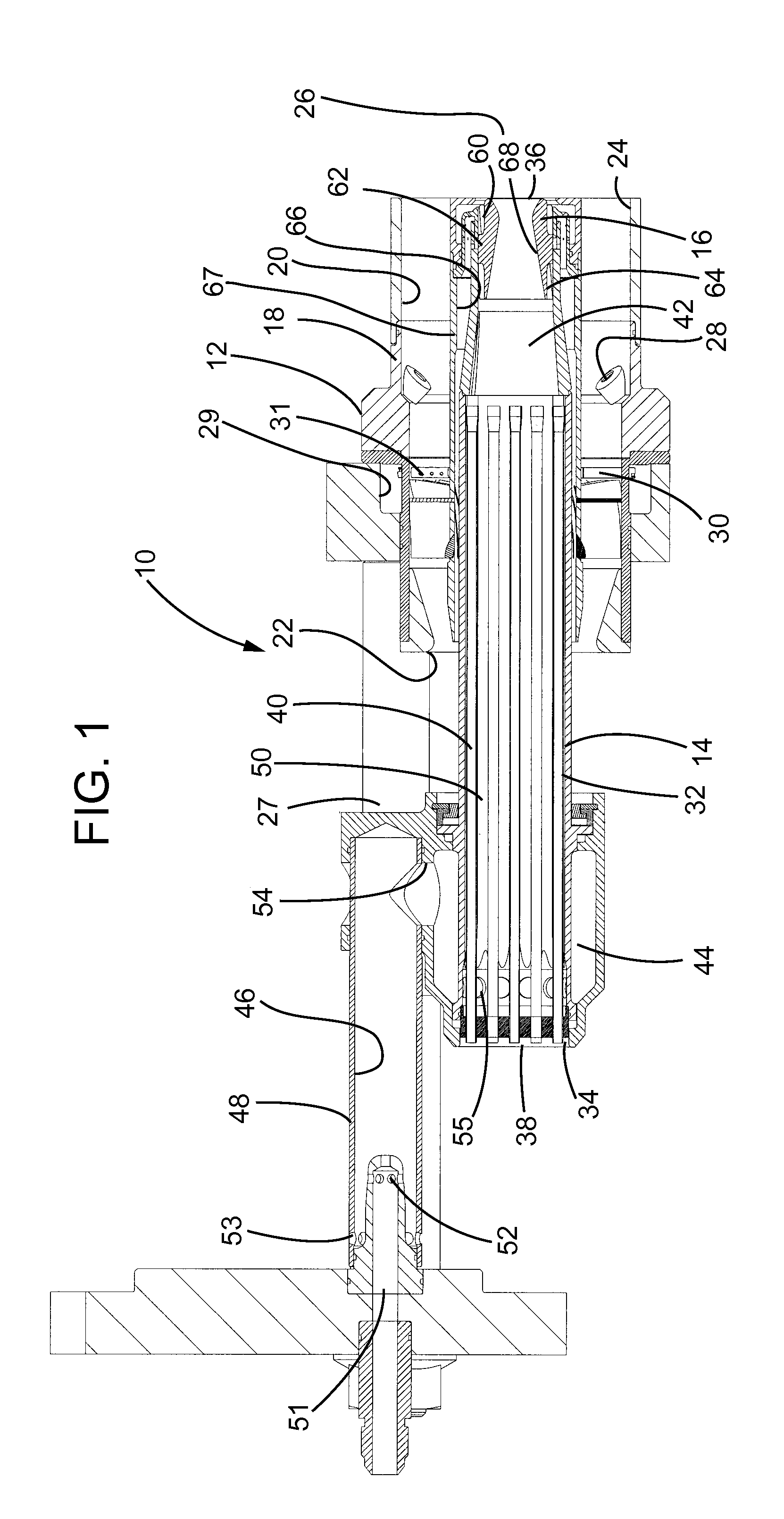
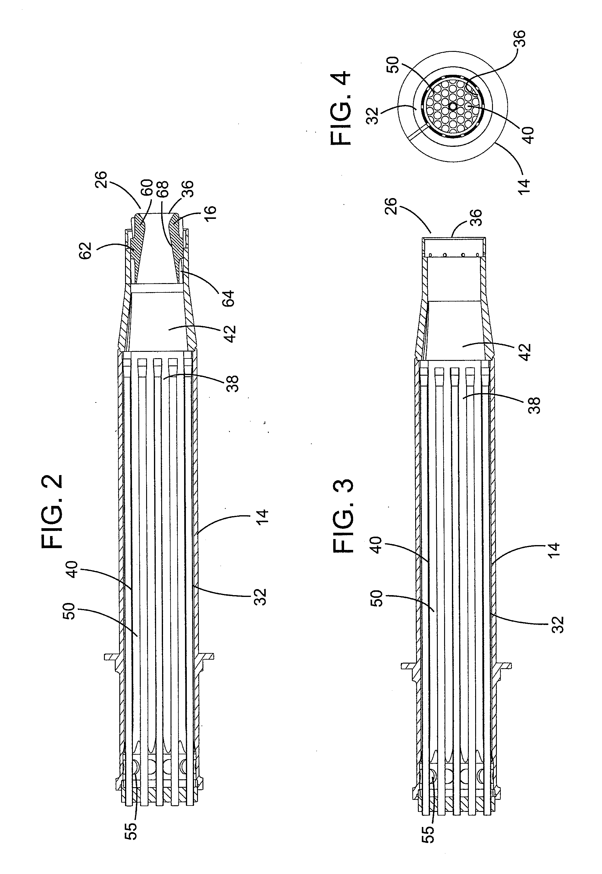
[0018]Turning now to the drawings, there is shown a cross-section of a fuel injector assembly 10 including a main injector 12 and a catalytic pilot 14 including a flow conditioner 16.

[0019]More specifically, in the illustrated embodiment, the injector 12 includes a housing 18 that forms at least one gas flow channel 20, or main swirler, having at least one upstream opening 22 and a downstream outlet 24 to a flame zone 26. The injector 12 itself may be of any appropriate design, including, for example, angled vanes to impart a swirl to the gasses flowing therethrough. The illustrated embodiment is adapted to utilize fuel gas or liquid fuel. In this regard, the housing 18 supports a plurality of nozzles 28 through which a liquid fuel may be provided. Alternately, fuel gas may be provided to the interior of the injector 12 by way of a supply line 27, which provides fuel to a circumferentially disposed plenum 29. The plenum 29 is fluidly connected to a plurality of radially disposed fue...


PUM


Abstract

An injector for a gas turbine combustor including a catalyst coated surface forming a passage for feed gas flow and a channel for oxidant gas flow establishing an axial gas flow through a flow conditioner disposed at least partially within an inner wall of the injector. The flow conditioner includes a length with an interior passage opening into upstream and downstream ends for passage of the axial gas flow. An interior diameter of the interior passage smoothly reduces and then increases from upstream to downstream ends.

Description

STATEMENT REGARDING FEDERALLY SPONSORED RESEARCH AND DEVELOPMENT[0001]This invention was made in part with the U.S. Government support under Contract DE-FC26-02CH11133 awarded by the Department of Energy to Precision Combustion Incorporated. The Government may have certain rights in this invention.TECHNICAL FIELD[0002]This patent disclosure relates generally to combustors and burners, and, more particularly to catalytic pilots for low emission gas turbine fuel injectors for use in combustors or burners.BACKGROUND[0003]Combustion is a major source of a class of pollutants including oxides of nitrogen, or NOx, (NO or nitric oxide, and NO2 or nitrogen dioxide), which may contribute to acid rain, smog, and ozone depletion. NOx emissions from combustion sources primarily consist of nitric oxide produced during combustion. When utilizing gaseous fuels, combustion processes that decrease the combustion temperature can greatly reduce the production of NO, and, accordingly, can have a signif...

Claims


Application Information

Patent Timeline
Patent Type & Authority Applications(United States)
IPC IPC(8): F23R3/40
CPCF23R3/343F23R3/40
Inventor DUTTA, PARTHASMITH, KENNETH O.RITZ, FRANK J.
Owner SOLAR TURBINES
Why Eureka
Try Eureka