Method for shot-peening and a shot-peening machine

a technology which is applied in the field of shot-peening and shot-peening machine, can solve the problems of increasing initial cost and increasing cost, and achieve the effect of reducing the cost of shot-peening and the roughness of the surface of the work

Active Publication Date: 2013-05-23
SINTOKOGIO LTD
View PDF8 Cites 9 Cited by
  • Summary
  • Abstract
  • Description
  • Claims
  • Application Information

AI Technical Summary

Benefits of technology

[0010]By using that shot-peening machine, the work can be processed by shot-peening wherein the shots are projected toward the work at the first speed for projecting the shots, and thereafter the shots are projected toward the work at the second speed for projecting the shots that is slower than the first speed for projecting the shots. Thus an intended distribution of compressive residual stresses is obtained by processing at the first and second speeds for projecting the shots and the surface roughness of the work is dec...

Problems solved by technology

Thus a long time is needed to complete the series of the processes, resulting in increasing the cost.
In contrast, respective shot-peening machines to which shots that are large in diameter are supplied and to which shots that are small in diameter are suppli...

Method used


Image

  • Method for shot-peening and a shot-peening machine
  • Method for shot-peening and a shot-peening machine
  • Method for shot-peening and a shot-peening machine

Examples


first embodiment

[0027]First, the first embodiment of the present invention is described.

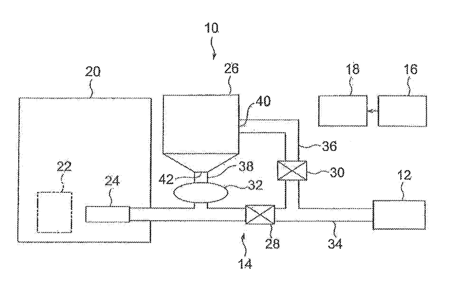
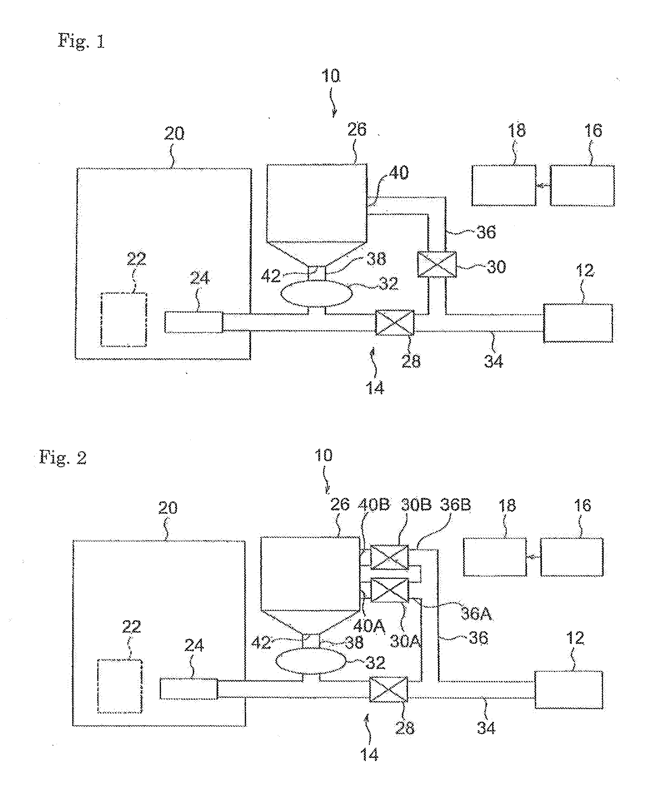
[0028]As in FIG. 1, the shot-peening machine 10 that is the first embodiment of the present invention comprises a device 12 for supplying compressed air, a projecting unit 14, an operating unit 16, a control unit 18, and a case 20.

[0029]The projecting unit 14 is used to project shots onto a work 22 that is housed in the case 20. It comprises a nozzle 24, a tank 26, flow control valves 28, 30, a valve 32 for controlling the amount of shots, and connecting piping 34, 36, 38.

[0030]The connecting piping 34 is connected to the device 12 for supplying compressed air. The nozzle 24 is attached to the end of the connecting piping 34. The nozzle 24 is located within the case 20 so that its jetting port faces the work 22. The middle portion in the longitudinal direction of the connecting piping 34 is connected to an inlet 40 of the tank 26 via the connecting piping 36. An outlet 42 of the tank 26 is connected to a point o...

second embodiment

[0069]Next, the second embodiment of the present invention is described.

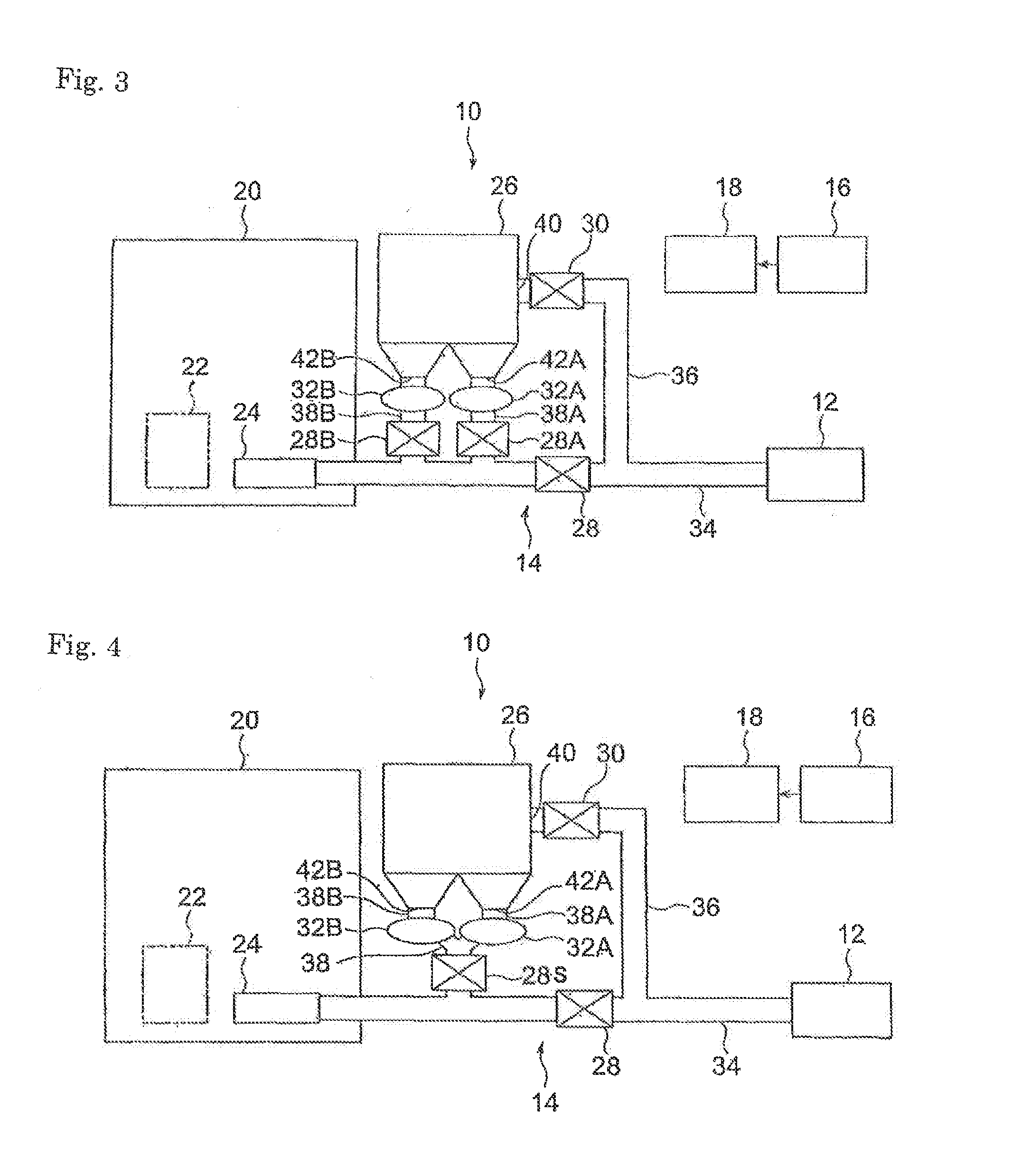
[0070]The shot-peening machine 110 as in FIG. 7 that is the second embodiment of the present invention is modified in its construction from the shot-peening machine 10 (see FIG. 1) of the first embodiment of the present invention as follows.

[0071]That is, the shot-peening machine 110 comprises a first projecting unit 114A and a second projecting unit 114B. The first projecting unit 114A comprises a first nozzle 124A, a first tank 126A, first flow control valves 128A, 130A, a first valve 132A for controlling the amount of shots, and connecting piping 134A, 136A, 138A. The second projecting unit 114B comprises a second nozzle 124B, a second tank 126B, second flow control valves 128B, 130B, a second valve 132B for controlling the amount of shots, and connecting piping 134B, 136B, 138B.

[0072]The first projecting unit 114A and the second projecting unit 114B are constructed the same as the projecting unit 14 of the f...


PUM

PropertyMeasurementUnit
Speedaaaaaaaaaa

Abstract

The cost for shot-peening is intended to be reduced. The method for shot-peening of the present invention comprises a first step for processing a work by shot-peening by projecting shots onto the work, and a second step for processing the work by shot-peening by projecting the shots onto the work at a speed for projecting the shots that is slower than the speed in the first step, wherein the second step uses the same shot-peening machine and same shots that have been used in the first step. By this method, an intended distribution of compressive residual stresses is obtained by the processes in the first and second steps and the surface roughness of the work is decreased by the process in the second step wherein the shots are projected at the speed that is slower than that in the first step. Further, no removal or supply of the shots and no re-setting of the conditions for the process that are related to the removal and supply of the shots are required. Multiple shot-peening machines do not need to be installed. Thus the cost for shot-peening is reduced.

Description

TECHNICAL FIELD[0001]The present invention relates to a method for shot-peening and a shot-peening machine.BACKGROUND ART [0002]Japanese Patent Laid-open Publication No. 2002-30344 discloses a method for shot-peening, wherein a work is processed by shot-peening that uses shots that are large in diameter, and then it is processed by shot-peening that uses shots that are small in diameter, so that a high residual stress is generated just below the surface of the work and the surface roughness is decreased.DISCLOSURE OF INVENTION[0003]If those processes by shot-peening are carried out by one shot-peening machine, shots that are large in diameter must be removed after the process by shot-peening that uses the large shots. Further, after that, shots that are small in diameter must be supplied and the conditions for the shot-peening must be adjusted for the shots. Thus a long time is needed to complete the series of the processes, resulting in increasing the cost.[0004]In contrast, respec...

Claims


Application Information

Patent Timeline
IPC IPC(8): B24C1/10
CPCB24C1/08B24C1/10
Inventor KOBAYASHI, YUJITSUJI, TOSHIYA
Owner SINTOKOGIO LTD
Why Eureka
Try Eureka