

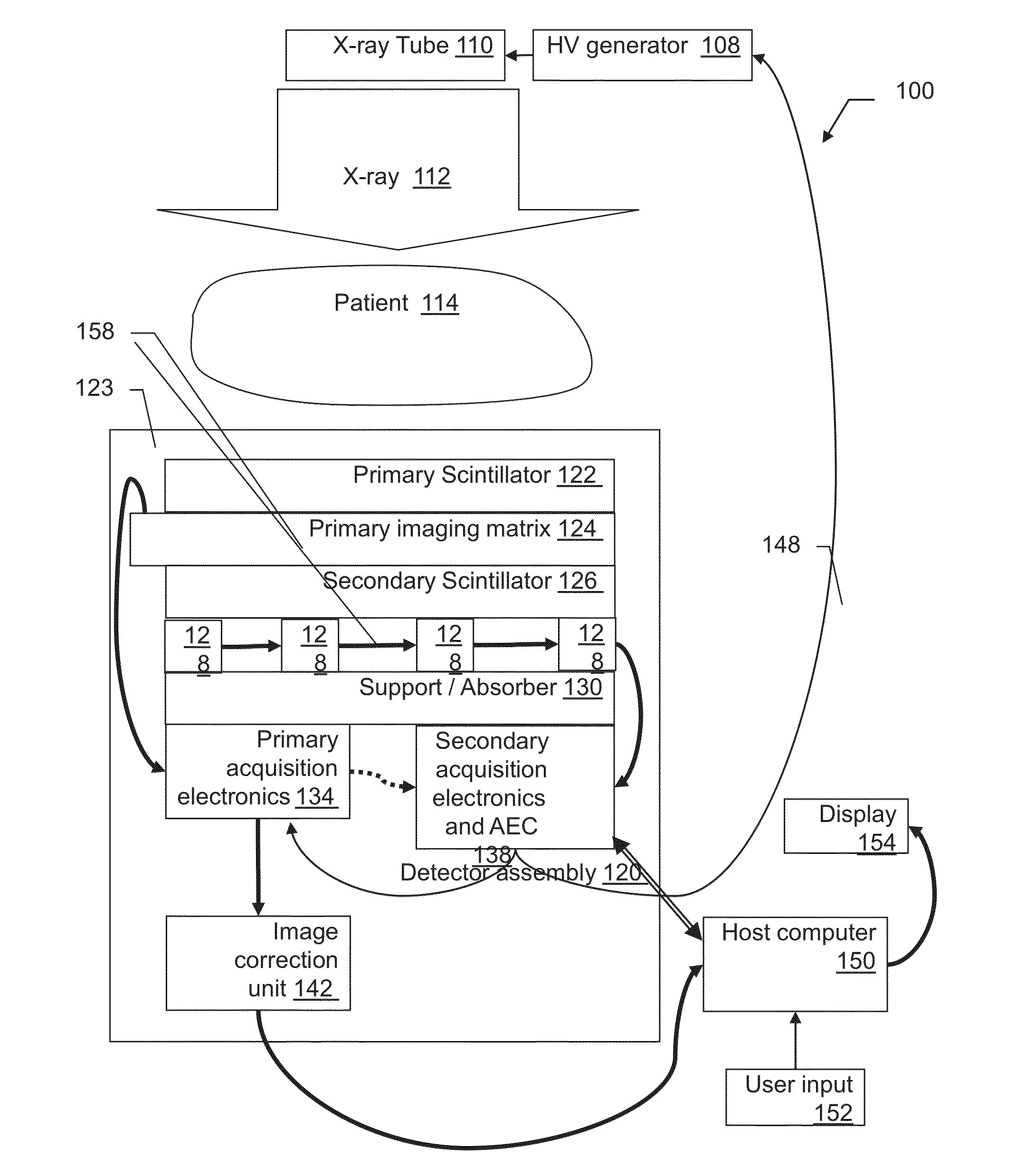
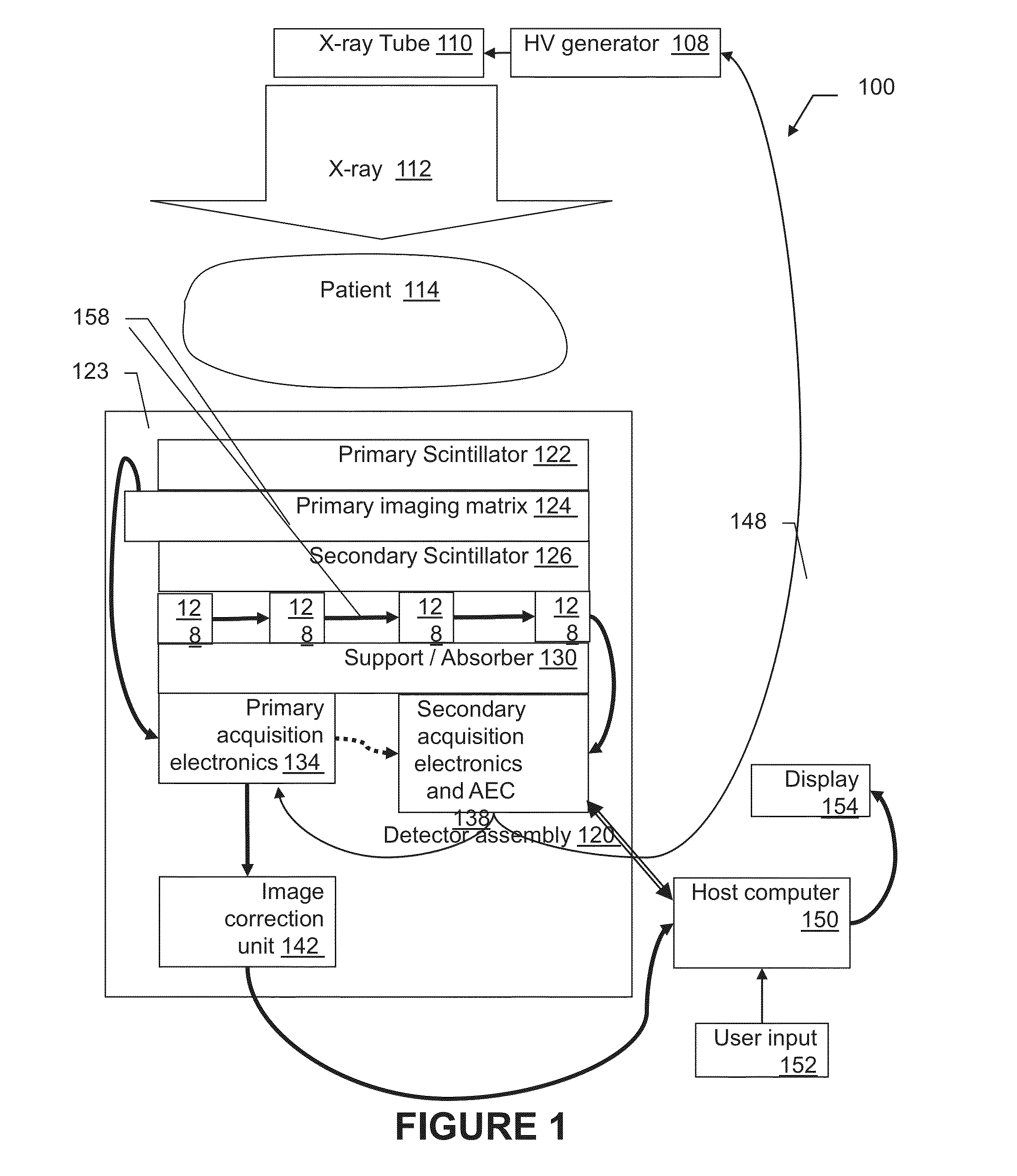
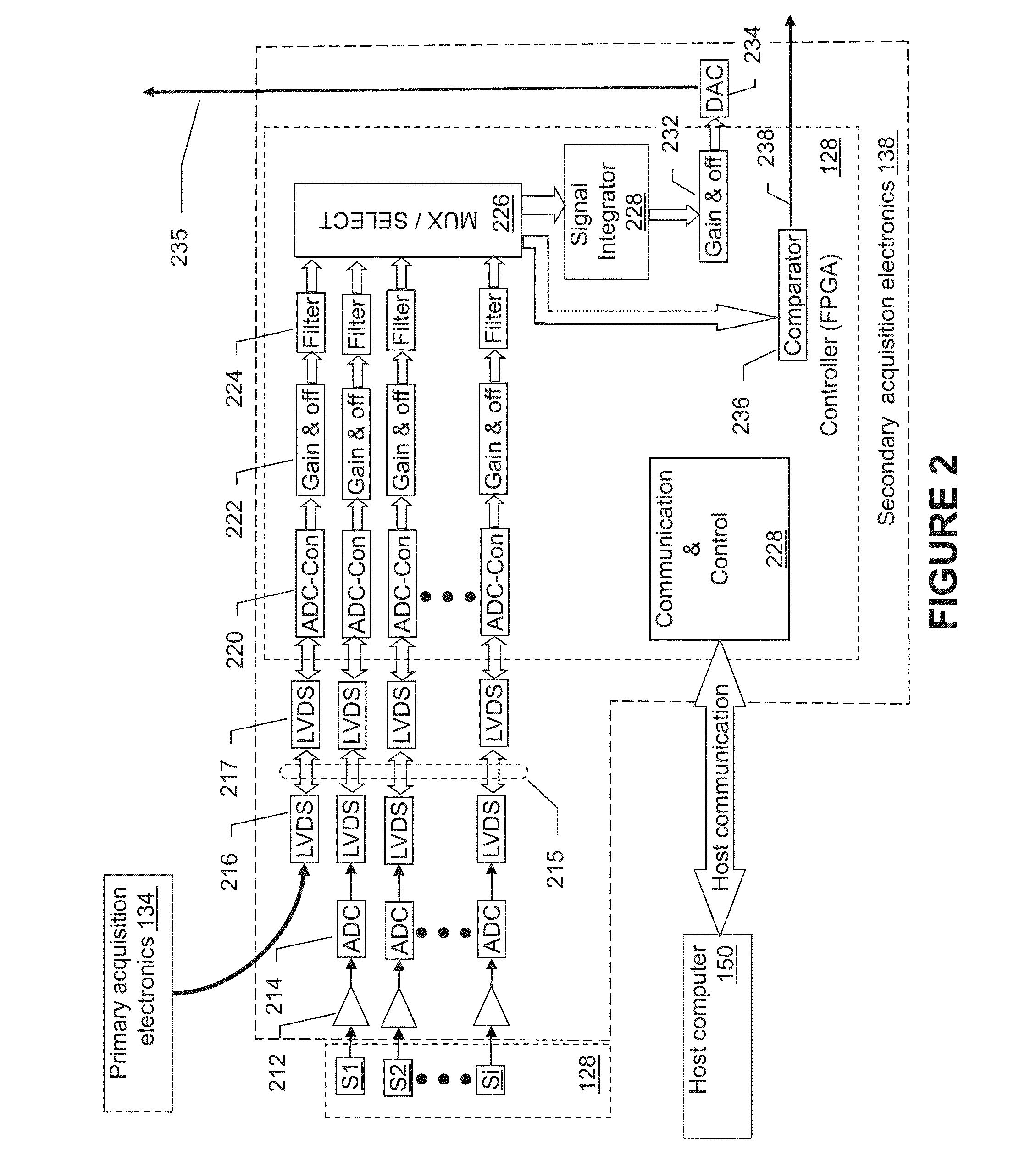
X-ray radiation detector with automatic exposure control
a radiation detector and automatic technology, applied in the direction of optical radiation measurement, photometry using electric radiation detectors, instruments, etc., can solve the problems of system host-dependent installation, interference with the proper fpd operation, and blockage of beams
- Summary
- Abstract
- Description
- Claims
- Application Information
AI Technical Summary
Benefits of technology
Problems solved by technology
Method used
Image

Examples
Embodiment Construction
[0065]Before explaining at least one embodiment of the invention in detail, it is to be understood that the invention is not limited in its application to the details of construction and the arrangement of the components set forth in the following description or illustrated in the drawings. The invention is capable of other embodiments or of being practiced or carried out in various ways. Also, it is to be understood that the phraseology and terminology employed herein is for the purpose of description and should not be regarded as limiting.
[0066]In discussion of the various figures described herein below, like numbers refer to like parts. The drawings are generally not to scale. For clarity, non-essential elements were omitted from some of the drawings.
[0067]To the extent that the figures illustrate diagrams of the functional blocks of various embodiments, the functional blocks are not necessarily indicative of the division between hardware circuitry. Thus, for example, one or more...
PUM
 Abstract
Description
Claims
Application Information