
Quasi-translator, fourier modulator, fourier spectrometer, motion control system and methods for controlling same, and signal processor circuit

a technology of quadratic transducer and spectrometer, applied in the direction of optical radiation measurement, interferometric spectrometry, instruments, etc., can solve the problems of system design and design difficulty of either solution, large size, and distortion of detected beams, so as to reduce the the effect of efficient, smooth and substantially error-free movement of the optical structure and motion-free movemen

Inactive Publication Date: 2013-05-30
PLX
View PDF17 Cites 16 Cited by
  • Summary
  • Abstract
  • Description
  • Claims
  • Application Information

AI Technical Summary

Benefits of technology

The invention is a motion control system and method that can accurately move a device and its optics smoothly without any errors. This allows for precise and reliable motion control.

Problems solved by technology

Any deviation from pure translation may cause slight tilting of a plane mirror, leading to distortion in the detected beam.
Typically, systems relying on either such solution have been difficult to design, relatively large, expensive and present maintenance issues.
However, such devices include structural deficiencies that do not provide pure, smooth translational motion, preferably with a broad arc, and substantially error-free motion regardless of orientation thereof.
For example, the rigid pendulum design of the Burkert device is inherently unbalanced (which leads to various problems, such as, but not limited to, the velocity of the pendulum not being compensated, the pivot point becomes stressed, etc.), and would not operate in any orientation.
While the Brierley device would also not operate in any orientation given the design thereof, further deficiencies of the complex design of the Brierley device requires an inordinate number of components, and unnecessary movement of those components, that add to economic cost and inefficiencies relating to manufacturing and maintaining same.
Additionally, such devices require complex re-calibration when switching those devices from one system to another, and such complex re-calibration can include an inordinate number of steps to perform same.
However, the extremely high machining tolerances required of such an arrangement and related issue of assembling same, result in high costs of both manufacture and maintenance.
In addition, such pure translation flexure mounts are not typically useful for the relatively large displacements necessary for high resolution applications.
The need for greater displacement can be achieved, but primarily through great cost of highly engineered precision instrumentation.
Such forces, jerkiness, velocity variations and resultant distortions introduce inaccuracies into the optical measurements and into the motion of the optics, such as a retroreflector.
A similarly pervasive issue concerns thermal and mechanical forces.
Additionally, a problem occurs when attempting to process and control one or more light / radiation source signals of such optical assemblies.
However, the problem with this method is sensitivity to pedestal shifts.
Unfortunately, the problem with this method is random injection of DC during turn around.
Such arrangements can result in zero velocity occurrences, which can result in various problems, such as, but not limited to, instability at thresholds, manifestations of incorrect / extra sample pulses that negatively affect the motion control and data collection of the optical assemblies, etc.

Method used


Image

  • Quasi-translator, fourier modulator, fourier spectrometer, motion control system and methods for controlling same, and signal processor circuit
  • Quasi-translator, fourier modulator, fourier spectrometer, motion control system and methods for controlling same, and signal processor circuit
  • Quasi-translator, fourier modulator, fourier spectrometer, motion control system and methods for controlling same, and signal processor circuit

Examples


Embodiment Construction

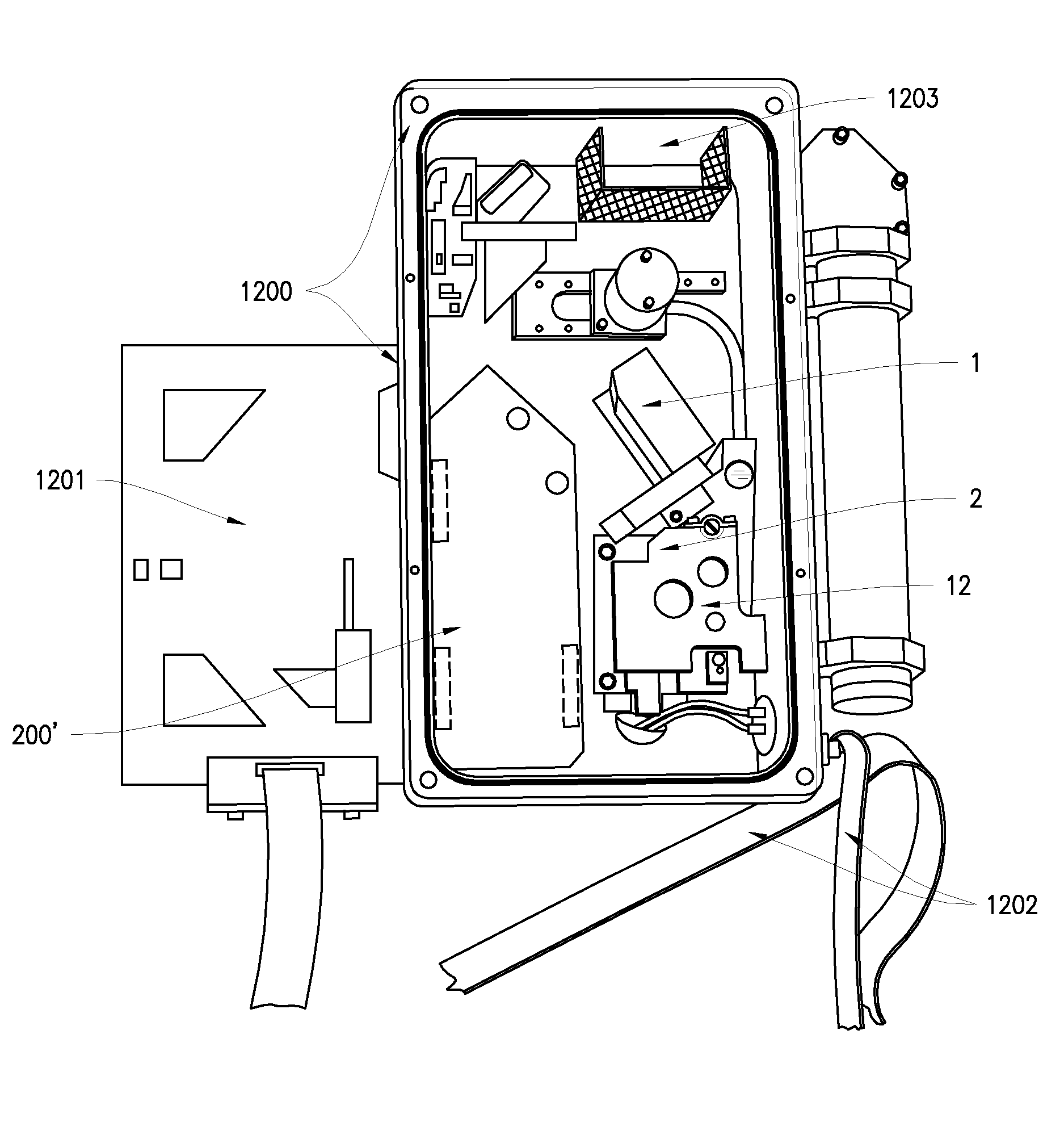
[0067]A quasi-translator / actuator / mirror moving mechanism, a Fourier modulator for use with the quasi-translator, a Fourier spectrometer for use with the quasi-translator, and a motion control system and method of use are disclosed herein. The quasi-translator operates as a moving mirror mechanism, and may have a support; an arm having a first end and a second end and including a driving magnet on the first end and a driven element on the second end; an axis, fixed in the support, transverse (e.g., perpendicular, substantially perpendicular, transverse, etc.) to the arm, acting as an axis of rotation of the arm; a bearing system fixed to or on the support, disposed on or along the axis, that operates to constrain or permit the arm to rotate about the axis substantially in or in a plane transverse (e.g., perpendicular, substantially perpendicular, etc.) to the axis; a drive coil substantially in or in the plane of rotation and fixed to the support; and a drive amplifier, connected to...


PUM


Abstract

A quasi-translator for economically producing pure, smooth translational motion with broad arcuate or error-free motion regardless of orientation, which is useful in numerous interferometer applications including spectroscopy, a Fourier modulator and a Fourier spectrometer are provided. The quasi-translator utilizes a support, an arm including a driving magnet on a first end and a driven element on a second end, an axis for rotation of the arm, a bearing system that controls the rotation of the arm about the axis, a drive coil and a drive amplifier to drive the arm in the arcuate motion. The quasi-translator may be employed in a Fourier modulator to change the optical path difference of the interferometer / quasi-translator at a substantially constant rate of change. The quasi-translator and / or Fourier modulator may be used in a Fourier spectrometer to create an optical spectrum from a light beam and / or electrical signal created from the light beam.

Description

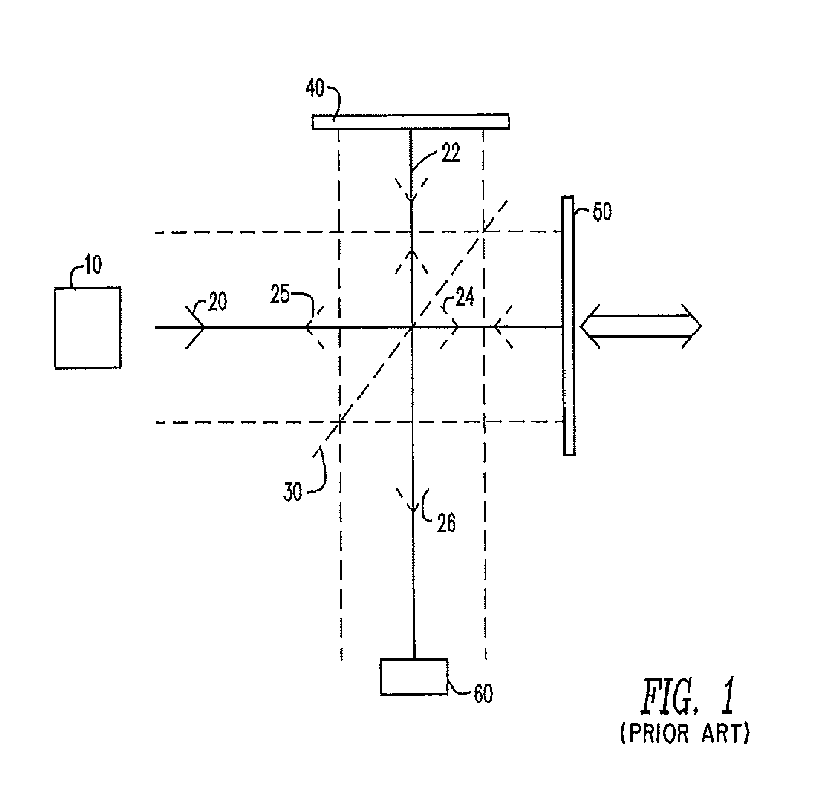
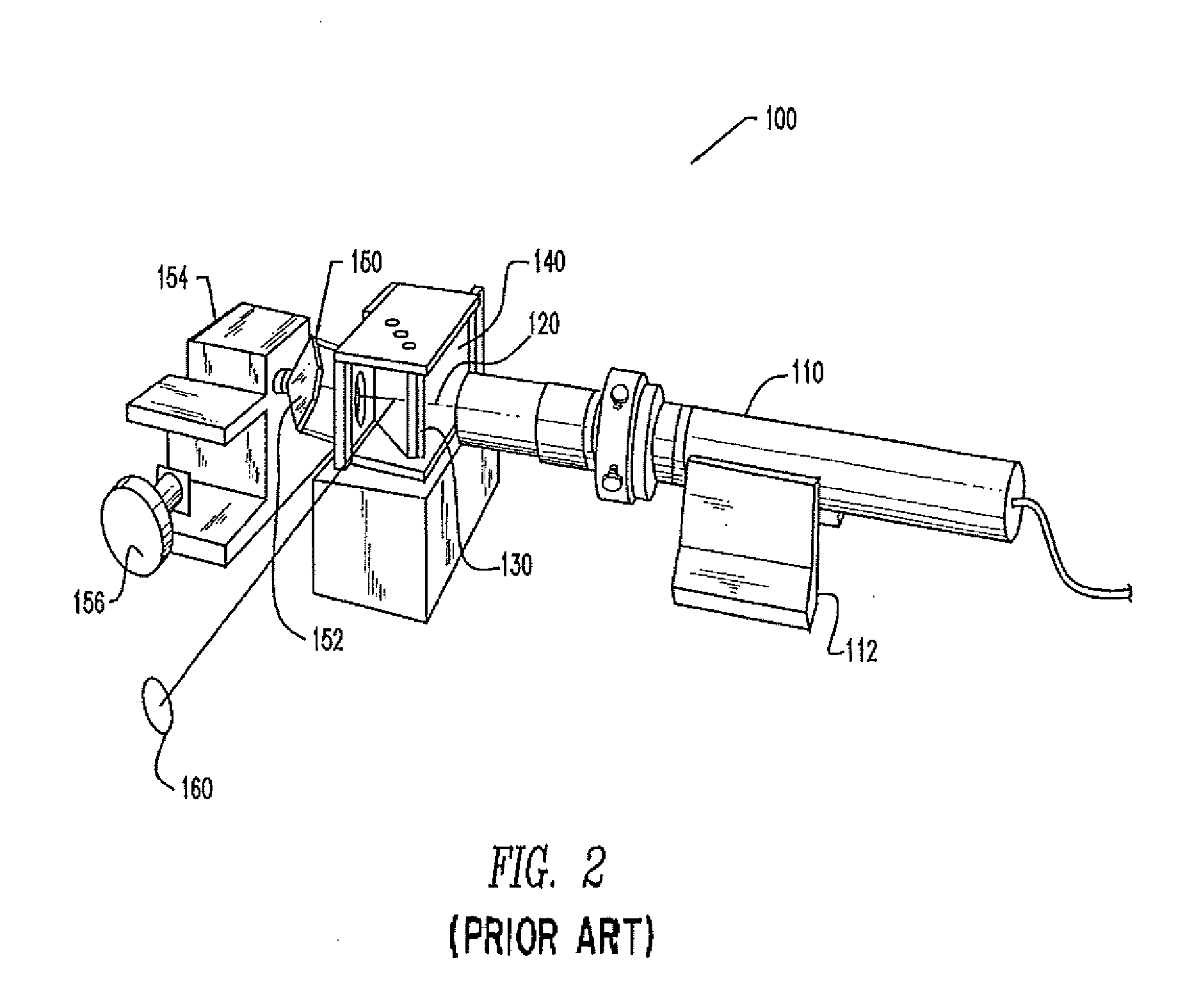
CROSS-REFERENCE TO RELATED APPLICATION(S)[0001]This application is a non-provisional patent application that claims the benefit of the filing date of, and priority to, U.S. Provisional Application No. 61 / 563,109, filed Nov. 23, 2011, the entirety of which is incorporated herein by reference.FIELD OF THE INVENTION[0002]The present invention is in the field of mechanisms for economically producing pure, smooth translational motion, preferably with a broad arc, and substantially error-free motion regardless of orientation and for motion control systems and methods of use thereof. Such substantially smooth translational motion is critical for precision instrumentation applications. One such application is the movement of optical assemblies, such as retroreflectors, mirrors, reflecting panels, etc., in interferometer / spectroscopy applications.BACKGROUND OF THE INVENTION[0003]Fourier transform infrared (“FTIR”) spectrometers are well known in the art. Michelson interferometers function by...

Claims


Application Information

Patent Timeline
IPC IPC(8): G01J3/45H02K33/16G05B6/02G02B26/00
CPCH03L5/00G01J3/45G02B26/00G05B6/02G01J3/4535G01B21/047G05B15/02G02B5/122G02B26/12H02K33/16
Inventor BLEIER, ZVIJACOBSON, ALEXANDERVIDRINE, DROUET WARRENKISSLINGER, JACK GORDON
Owner PLX
Learn More