System and method providing over current protection based on duty cycle information for power converter

a technology of duty cycle information and power converter, which is applied in the direction of power conversion systems, dc-dc conversion, electrical apparatus, etc., can solve the problems of transformer secondary side rectifier components being subject to permanent damage, current can reach a level, and the effect of wide application rang

Active Publication Date: 2013-05-30
ON BRIGHT ELECTRONICS SHANGHAI
View PDF3 Cites 72 Cited by
  • Summary
  • Abstract
  • Description
  • Claims
  • Application Information

AI Technical Summary

Benefits of technology

[0003]The present invention is directed to integrated circuits. More particularly, the invention provides a control system and method for over-current protection and over-power protection. Merely by way of example, the invention has been applied to a power converter. But it would be recognized that the invention has a much broader range of applicability.

Problems solved by technology

If the OCP system is not effective, the current can reach a level at which damage to the switch is imminent due to excessive current and voltage stress at switching or thermal run-away during operation.
Consequently, the rectifier components on the transformer secondary side are subject to permanent damage due to excessive voltage and current stress in many offline flyback converters.
This limitation on maximum power can protect the power converter from thermal run-away.
Some conventional OCP systems use an adjustable OCP threshold value based on line input voltage, but the actual limitation on maximum current and thus maximum power is not always constant over a wide range of line input voltage.
But the resistor 152 consumes significant power, which often is undesirable for meeting stringent requirements on low standby power.
Therefore the power can be limited by controlling the current limit ILimit.

Method used


Image

  • System and method providing over current protection based on duty cycle information for power converter
  • System and method providing over current protection based on duty cycle information for power converter
  • System and method providing over current protection based on duty cycle information for power converter

Examples


Embodiment Construction

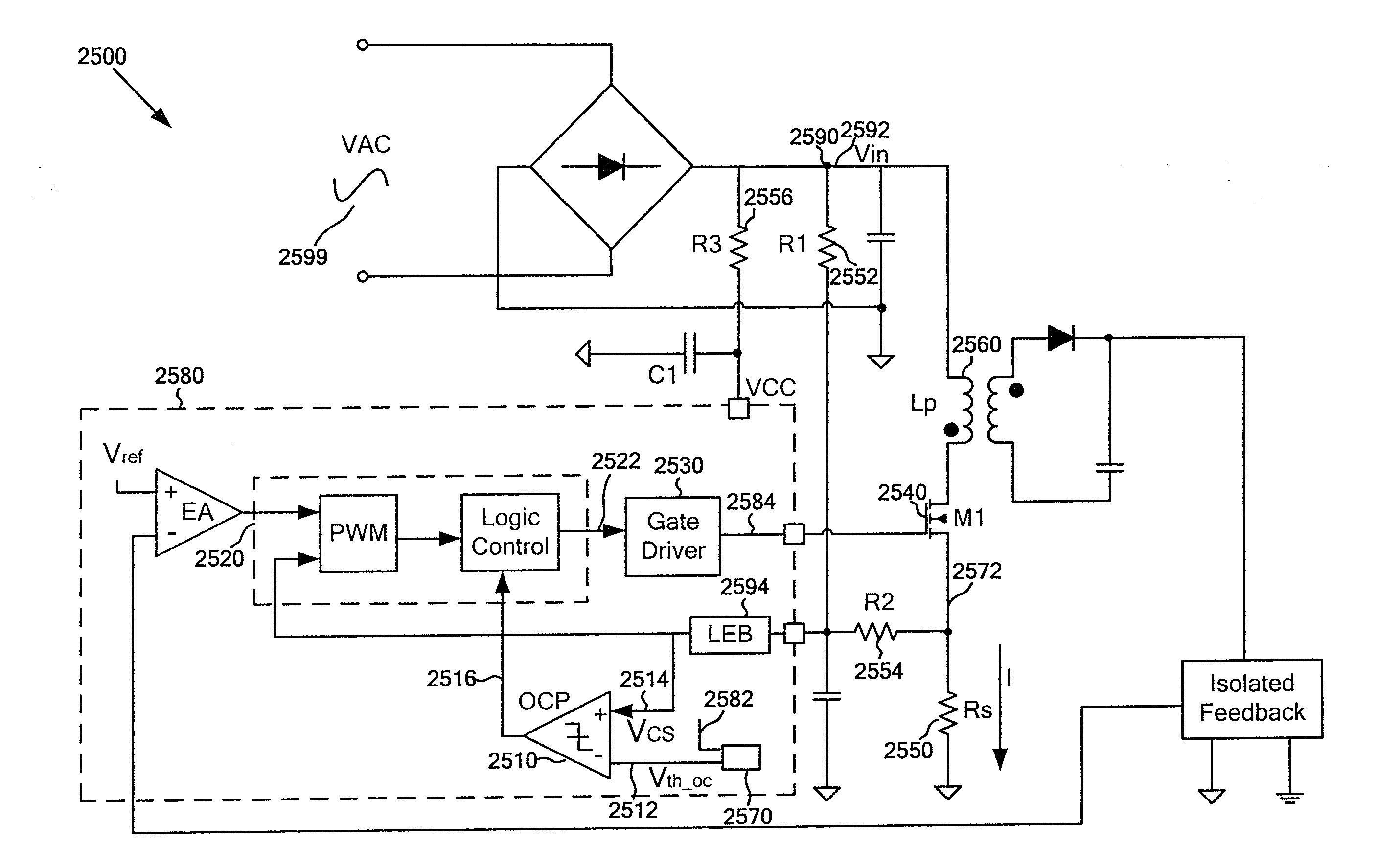
[0070]The present invention is directed to integrated circuits. More particularly, the invention provides a control system and method for over-current protection and over-power protection. Merely by way of example, the invention has been applied to a power converter. But it would be recognized that the invention has a much broader range of applicability.

[0071]FIGS. 8 and 9 are simplified timing diagrams for a switch-mode converter corresponding to different bulk voltages in the CCM mode. For example, the bulk voltage for FIG. 8 is higher than the bulk voltage for FIG. 9.

[0072]As shown in FIG. 8, curves 2810, 2820, 2830, and 2840 represent the timing diagrams for a clock signal (e.g., CLK), a PWM signal (e.g., PWM), an over-current threshold signal (e.g., Vth—oc), and a current sensing signal (e.g., VCS) respectively. For example, the clock signal is in sync with the PWM signal. In another example, the PWM signal is generated by a PWM controller component. In yet another example, the...


PUM


Abstract

System and method for protecting a power converter. An example system controller for protecting a power converter includes a signal generator, a comparator, and a modulation and drive component. The signal generator is configured to generate a threshold signal. The comparator is configured to receive the threshold signal and a current sensing signal and generate a comparison signal based on at least information associated with the threshold signal and the current sensing signal, the current sensing signal indicating a magnitude of a primary current flowing through a primary winding of a power converter. The modulation and drive component is coupled to the signal generator.

Description

1. CROSS-REFERENCES TO RELATED APPLICATIONS[0001]This application claims priority to Chinese Patent Application No. 201310015152.4, filed Jan. 15, 2013, commonly assigned, incorporated by reference herein for all purposes. In addition, this application is a continuation-in-part of U.S. patent application Ser. No. 13 / 005,427, filed Jan. 12, 2011, claiming priority to Chinese Patent Application No. 201010587658.9, filed Dec. 8, 2010, both of these applications being commonly assigned and incorporated by reference herein for all purposes.[0002]Additionally, this application is related to U.S. patent application Ser. Nos. 11 / 213,657, 12 / 125,033, 11 / 752,926, 12 / 690,808, and 13 / 205,417, commonly assigned, incorporated by reference herein for all purposes.2. BACKGROUND OF THE INVENTION[0003]The present invention is directed to integrated circuits. More particularly, the invention provides a control system and method for over-current protection and over-power protection. Merely by way of ex...

Claims


Application Information

Patent Timeline
Patent Type & Authority Applications(United States)
IPC IPC(8): H02H9/02
CPCH02H9/025H02M3/33507H02M1/32H02M1/0009H02M1/08H02M3/156H02M3/33515
Inventor YAO, CHAOZHANG, YUNCHAOLIN, YUANSUN, ZHIQIANGFANG, LIEYI
Owner ON BRIGHT ELECTRONICS SHANGHAI
Why Eureka
Try Eureka