Wind turbine air flow guide device

Inactive Publication Date: 2013-05-30
WOJNAR SEBASTIAN
View PDF7 Cites 17 Cited by
  • Summary
  • Abstract
  • Description
  • Claims
  • Application Information

AI Technical Summary

Benefits of technology

[0029]The invention further extends to a method of guiding air flow relative to a wind turbine, the method including the steps of forming a first air flow channel having an inlet and an outlet and which increases a volumetric flow rate of air from the inlet towards the wind turbine and the outlet, and forming a second air flow channel which flows adjacent the first air flow channel and which increases the volumetric flow rate of air towards an outlet of the second air flow channel so that air flowing through the outlet of the second air flow channel entrains at least partly air flowing from the outlet of the first air flow channel.
[0030]In another form of the invention, there is also provided for a method of guiding air flow relative to a wind turbine, the method including the steps of forming a first air flow channel having an inlet and an outlet and which increases a volumetric flow rate of air from the inlet towards the wind turbine and the

Problems solved by technology

However, wind turbines often have to operate in low wind speed conditions which reduce the efficiency of the wind turbine.
However, this solution suffers from a number of difficulties including requiring a complex operating system making us

Method used


Image

  • Wind turbine air flow guide device
  • Wind turbine air flow guide device
  • Wind turbine air flow guide device

Examples


Embodiment Construction

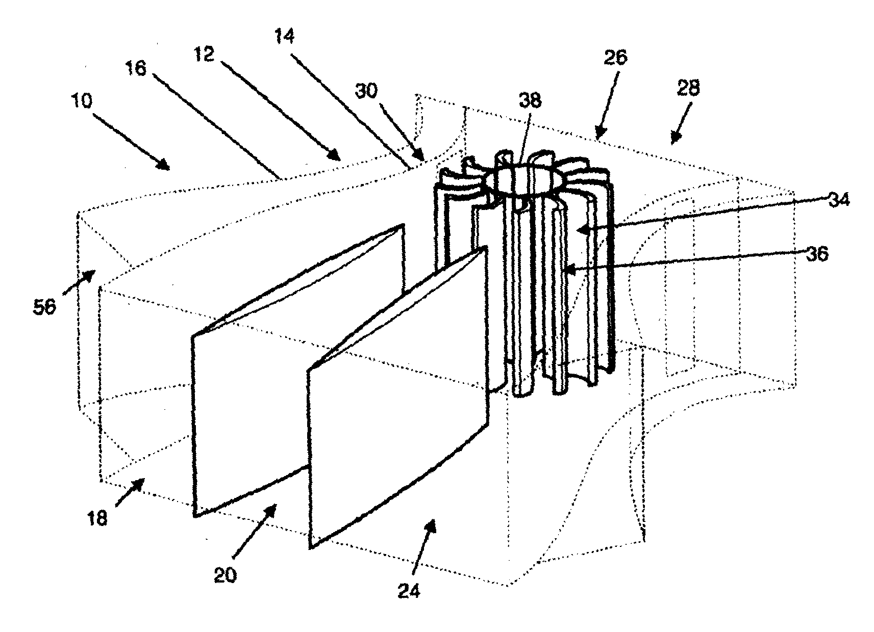
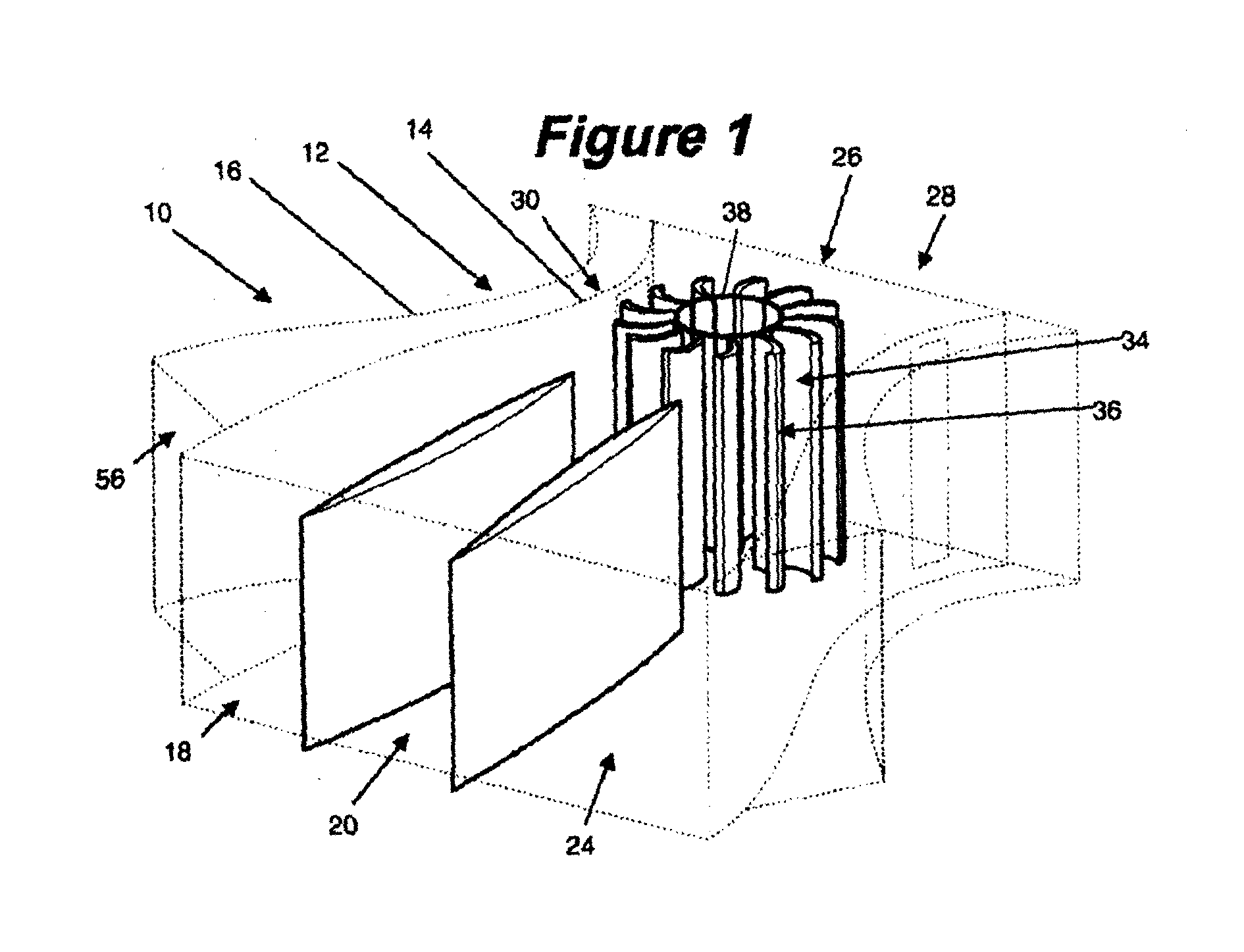
[0045]FIG. 1 of the accompanying illustrations shows a wind turbine air flow device 10 according to the principles of the invention. The wind turbine airflow device has a body 12 having an inner side wall 14 and an outer side wall 16. The inner side wall defines a channel 18 which extends through the body. Also defined by the inner side wall is an inlet portion 20 which defines an inlet 24 to the channel, an outlet portion 26 which defines an outlet 28 from the channel, and an intermediate portion 30 which is positioned between the inlet and outlet portions.

[0046]Positioned inside the intermediate portion is a vertical axis wind turbine 34. The wind turbine 34 has a number of blades 36 which extend from a central core 38 of the wind turbine.

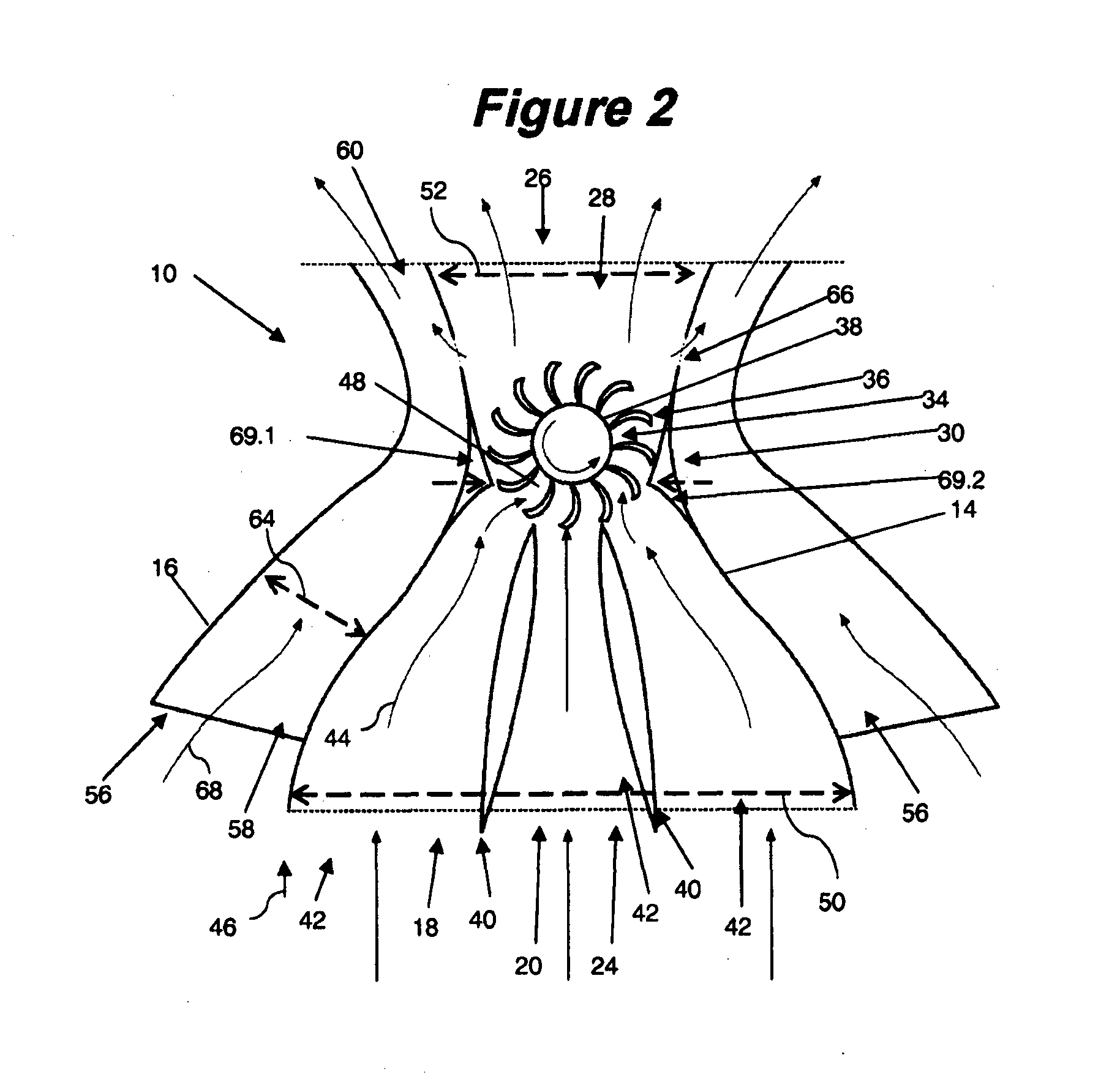
[0047]Referring to FIG. 2, the inlet portion 20 has two guide vanes 40 which extend into the channel 18 from the inlet 24. The guide vanes 40 divide the channel 18 at the inlet portion 20 into a number of Venturi flow paths 42 which devices a por...


PUM


Abstract

The invention extends to an air flow device for wind turbines which includes a number of flow paths which assist in the movement of air through the air flow device which assists in increasing the efficiency and power output of the wind turbine. The air flow device includes flow passages alongside a central channel which houses the wind turbine.

Description

FIELD OF THE INVENTION[0001]The invention generally relates to an air flow device and more particularly is concerned with an air flow device for use with a wind turbine.[0002]Whilst the invention may be applied to any type of wind turbine, for convenience sake it shall be described herein in terms of an air flow device for use with wind turbines such as vertical axis wind turbines (VAWT).BACKGROUND TO THE INVENTION[0003]Generally the power output of a wind turbine is dependent on the velocity with which air flows past the wind turbine. In other words, greater air speeds normally allow wind turbines to generate more electricity. However, wind turbines often have to operate in low wind speed conditions which reduce the efficiency of the wind turbine.[0004]A number of solutions have been devised in the past to allow wind turbines, normally having horizontal axes (hereinafter referred to as HAWT), to operate more efficiently at low ambient wind speed conditions.[0005]For example, United...

Claims


Application Information

Patent Timeline
IPC IPC(8): F03D1/04F03D3/04
CPCF03D1/04F03D3/0427Y02E10/74Y02B10/30Y02E10/72F05B2240/133F03D3/02
Inventor WOJNAR, SEBASTIAN
Owner WOJNAR SEBASTIAN
Why Eureka
Try Eureka