Method for producing coating layer with low-friction

a coating layer and low friction technology, applied in the direction of roads, traffic signals, transportation and packaging, etc., can solve the problems of insufficient friction characteristics at both high and low temperature and low abrasion resistance, limited application to various drive components, and relatively long friction stable sections

Inactive Publication Date: 2013-05-30
HYUNDAI MOTOR CO LTD
View PDF4 Cites 1 Cited by
  • Summary
  • Abstract
  • Description
  • Claims
  • Application Information

AI Technical Summary

Benefits of technology

[0012]The present invention has been made in an effort to solve the above-described problems associated with prior art. It is an object of the present invention to provide a method for producing a coating layer with low-friction, and, in particular, a method which forms nano-sized Ag particles on a surface by controlling processing conditions (bias voltage, sputter power and the like) to form the coating layer. The present methods provide a coating layer having a superior low-friction property as compared to a conventional coating layer.

Problems solved by technology

While DLC coatings are advantageously already mass-produced and have been broadly used, it has insufficient friction characteristic at both high and low temperature and low abrasion resistance.
Further, it also has a relatively long friction stable section, which is problematic.
However, due to insufficient low-friction properties, its application to various drive components is limited.
However, the initial low-friction property is still limited and, further, it is difficult to carefully control the Ag fraction as needed.

Method used


Image

  • Method for producing coating layer with low-friction
  • Method for producing coating layer with low-friction
  • Method for producing coating layer with low-friction

Examples


Embodiment Construction

[0028]Hereinafter, a method for producing a coating layer with low-friction according to the preferred embodiments of the present invention now will be described in detail with reference to the accompanying drawings.

[0029]It is understood that the term “vehicle” or “vehicular” or other similar term as used herein is inclusive of motor vehicles in general such as passenger automobiles including sports utility vehicles (SUV), buses, trucks, various commercial vehicles, watercraft including a variety of boats and ships, aircraft, and the like, and includes hybrid vehicles, electric vehicles, plug-in hybrid electric vehicles, hydrogen-powered vehicles and other alternative fuel vehicles (e.g. fuels derived from resources other than petroleum). As referred to herein, a hybrid vehicle is a vehicle that has two or more sources of power, for example both gasoline-powered and electric-powered vehicles.

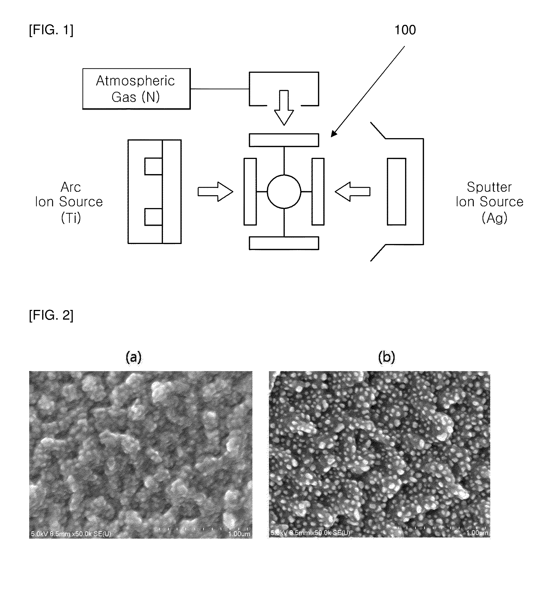
[0030]FIG. 1 is a configuration diagram of a coating device to conduct the method for produ...


PUM

PropertyMeasurementUnit
temperatureaaaaaaaaaa

Abstract

In a method for producing a coating layer using plasma which includes heating, buffer layer coating, coating and cooling, a method for producing a coating layer with low-friction comprises: a coating step of forming TiAgN coating layer on the surface of a base material using Ti arc source and Ag sputtering source at a certain coating temperature; a fraction increase step of increasing the Ag fraction on the surface by increasing bias voltage and sputtering power for a certain time period; and a nano-forming step of forming Ag nanoparticles on the surface by maintaining the temperature at 50˜100° C. higher than the certain coating temperature for a certain time period.

Description

CROSS-REFERENCE TO RELATED APPLICATION[0001]This application claims under 35 U.S.C. §119(a) the benefit of Korean Patent Application No. 10-2011-0124270 filed on Nov. 25, 2011, the entire contents of which are incorporated herein by reference.BACKGROUND[0002](a) Technical Field[0003]The present disclosure relates to a method for producing a coating layer having low-friction, and more particularly to a method which forms nano-sized Ag particles on a surface by controlling processing conditions (bias voltage, sputter power and the like) to form the coating layer.[0004](b) Background Art[0005]Typically, a plasma coating technique is used to coat a material on an untreated base material using plasma phenomenon under vacuum condition. Such coatings can add mechanical and functional characteristics that an original base material does not have. Plasma coating techniques are commonly divided to CVD (Chemical vapor deposition) and PVD (Physical vapor deposition).[0006]As PVD techniques, vacu...

Claims


Application Information

Patent Timeline
Patent Type & Authority Applications(United States)
IPC IPC(8): C23C14/34B32B3/10
CPCH01J37/34H01J37/32055H01J37/3497Y10T428/24372C23C14/325C23C14/3492C23C14/58C23C14/0641C23C14/34
Inventor LYO, IN WOONGHONG, WOONG PYOCHOI, KWANG HOONKANG, HYUK
Owner HYUNDAI MOTOR CO LTD
Why Eureka
Try Eureka