Means to Track the Cumulative Compressions Imparted to a Shoe

a technology of cumulative compression and shoe, applied in the field of shoes, can solve the problems of inefficiency and injury, inability to detect the cumulative destruction of the shoe by a simple external examination, and injuries caused,

Inactive Publication Date: 2013-06-06
PARAWARE
View PDF4 Cites 18 Cited by
  • Summary
  • Abstract
  • Description
  • Claims
  • Application Information

AI Technical Summary

Benefits of technology

[0017]The invention is further described by the method of its use with a shoe to measure the accumulating destructive compressions which include the steps of: (1) inserting the device into the shoe; (2) using the shoe in a destructive way; (3) the user activating the user interface; (4) the user deciding to co

Problems solved by technology

Athletes must replace their shoes as the midsole foam wears due to the cumulative destructive compressions that occur from use.
Delaying the replacement of the shoe will lead to injuries caused by the lower extremities absorbing more of the impact.
In addition, changes in the characteristics of the midsole foam, such as shape and compression resistance, affects the users ability to control their biomechanical motion during their stance to foot swing phase, also known as the gait of the user, causing inefficiency and injury.
Because the construction of the midsole includes microporous foam, detection of this cumulative destruction cannot be determined by a simple external examination.
As with other microscopic failure modes, examining a device in a static condition does not predict the loss of performance in a kinetic condition, such as during a runner's heel strike through the roll off the toe.
A disadvantage of the prior art is the placement of the device within the construction of the shoe, which requires that the design and manufacturing process of the shoe be altered.
Furthermore, this requirement leads to the reduction in performance of the shoe both by the elimination of a portion of the cushioning foam and reduction in flexibility due to the addition of the device.
For example, the placement of the device within the midsole or outsole requires the reengineering of the shoe to compensate for the loss of functionality, which would disallow the device from being incorporated in any existing shoe designs.
Another disadvantage of the prior art is the requirement of the sensor to be a combination of an air bladder and pressure sensor or a combination of an accelerator and force sensing resistor.
These disadvantages require a robust and complex analysis of the starting and ending state of the sensor throughout the shoe use and, in some cases, foreknowledge of the wear rate of the shoe.
Another disadvantage of

Method used


Image

  • Means to Track the Cumulative Compressions Imparted to a Shoe
  • Means to Track the Cumulative Compressions Imparted to a Shoe
  • Means to Track the Cumulative Compressions Imparted to a Shoe

Examples


Embodiment Construction

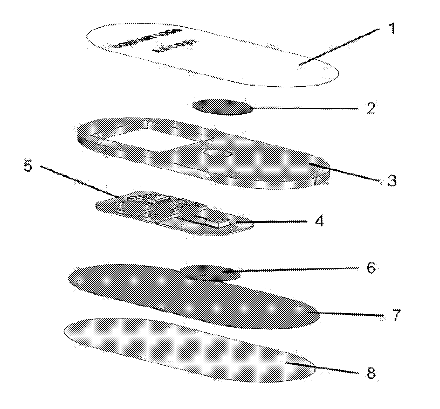
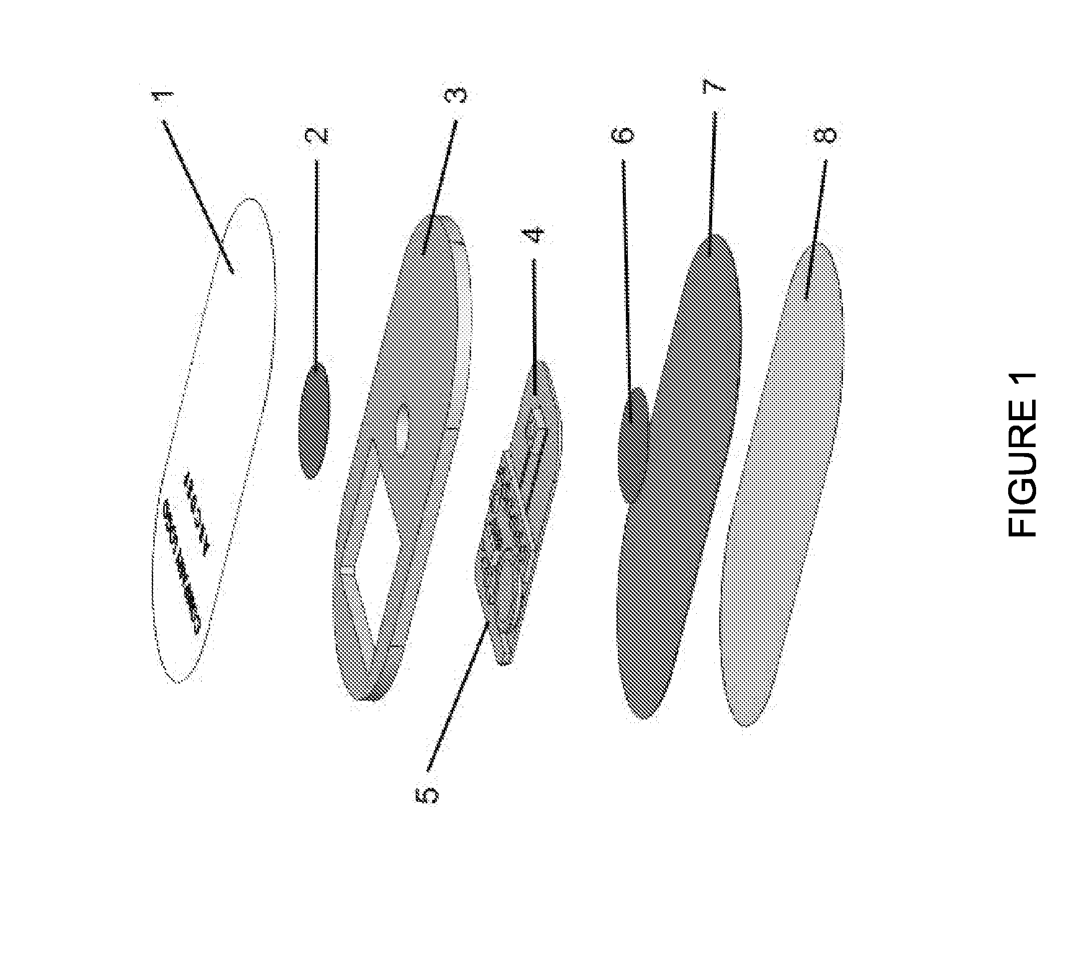
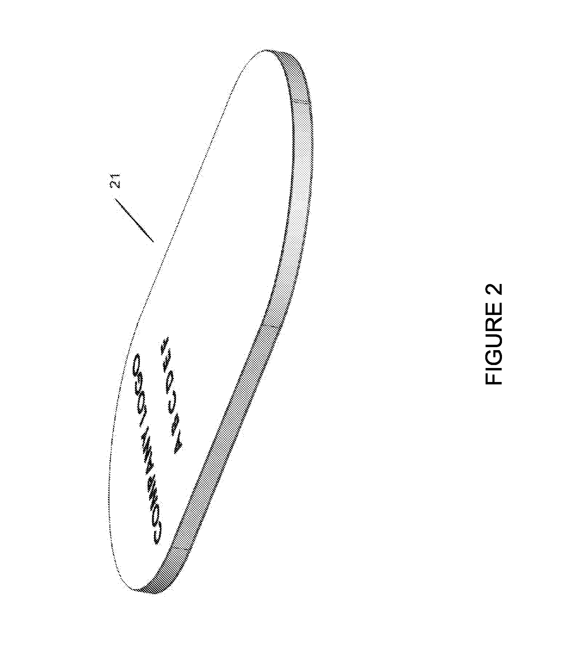
[0033]As shown in FIG. 2, the inventive device 21 comprises an assembly of components, which are shown in the exploded view in FIG. 1. The device 21 comprises an assembly of the upper enclosing layer 1, the upper substantially rigid member 2, the microporous highly compressible foam member 3, the highly compressible area containing the electromechanical switch circuit 4, the highly incompressible area containing the electronic analysis components 5, the lower substantially rigid member 6, the flexible substrate 7, and the lower enclosing layer 8.

[0034]In operation, the device 21 would be placed within the shoe under the sock liner, or insole, toward the heel and in contact with the upper side of the energy absorbing foam in the heel of the shoe, as shown in FIG. 3. The user would then engage in an activity, such as walking or running, which causes a force to be applied to the system, thereby causing partial failure of the energy absorbing foam. Although a single cycle of the force f...


PUM


Abstract

A device, inserted in a running shoe is used to track the accumulation of destructive compression cycles within the shoe and to indicate this information to the user through a series of integrated indicators. The device has an advantage of being able to be placed in any shoe without compromising the construction or performance of the shoe. An additional advantage of the invention is the improved accuracy of the information by improving both the stability and longevity of the sensor system and the ability to distinguish destructive, partially destructive and nondestructive compressions. Another advantage of the invention is the reduction of the cost of construction while achieving a lifetime in excess of the shoe. Yet another advantage of the invention is the user interface, which is contained completely within the device allowing the user to view the information within the shoe.

Description

[0001]This application claims priority of U.S. Provisional Patent Application Ser. No. 61 / 567,316, filed Dec. 6, 2011, the disclosure of which is incorporated herein by reference in its entirety.BACKGROUND OF THE INVENTION[0002]The present invention relates generally to a shoe having an ability to track the cumulative destructive compressions imparted to a shoe by its user and the ability to indicate that information to the user. More specifically, the present invention relates to an attachment of the shoe that measures the destructive compressions of the shoe, accumulates those compressions and displays the accumulation to the user.[0003]Athletes must replace their shoes as the midsole foam wears due to the cumulative destructive compressions that occur from use. Delaying the replacement of the shoe will lead to injuries caused by the lower extremities absorbing more of the impact. In addition, changes in the characteristics of the midsole foam, such as shape and compression resist...

Claims


Application Information

Patent Timeline
IPC IPC(8): G01N3/34
CPCG01N2203/0244G01N3/56A43B3/0005G01N3/342A43B3/34
Inventor BURKE, AARONJANNSEN, DANIELSMID, DERKHILLS, ANDREW
Owner PARAWARE
Why Eureka
Try Eureka