System and method for improving transition lift-fan performance

Active Publication Date: 2013-06-06
AURORA FLIGHT SCI CORP
View PDF65 Cites 40 Cited by
  • Summary
  • Abstract
  • Description
  • Claims
  • Application Information

AI Technical Summary

Benefits of technology

[0012]In some aspects, the inactive lift fans may be covered after

Problems solved by technology

Unfortunately, a disadvantage associated with ducted lift-fan aircraft is momentum drag, which causes an aircraft to require much higher power levels.
This reduces the power needed to produce the required lift; however, the ass

Method used


Image

  • System and method for improving transition lift-fan performance
  • System and method for improving transition lift-fan performance
  • System and method for improving transition lift-fan performance

Examples


Embodiment Construction

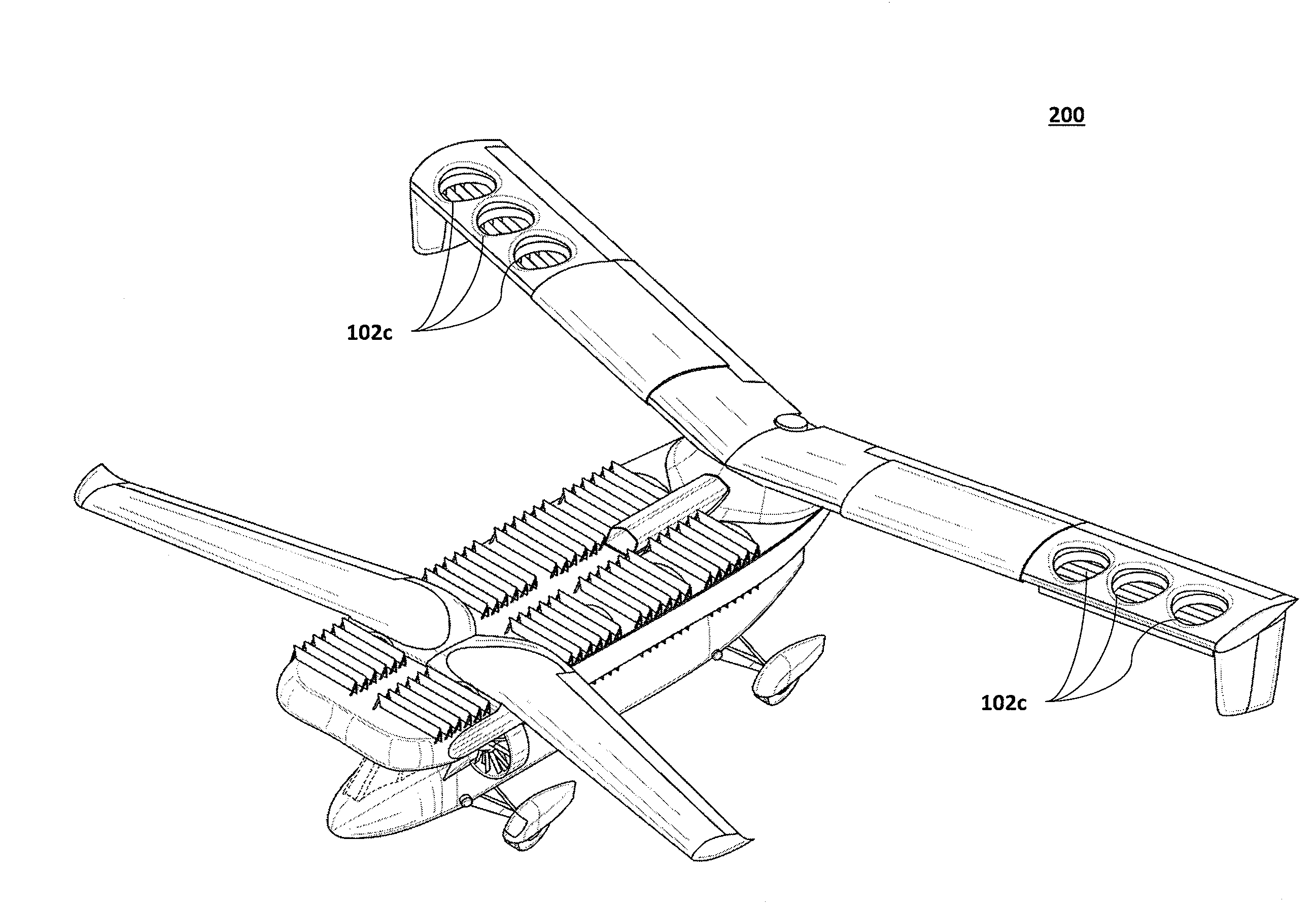
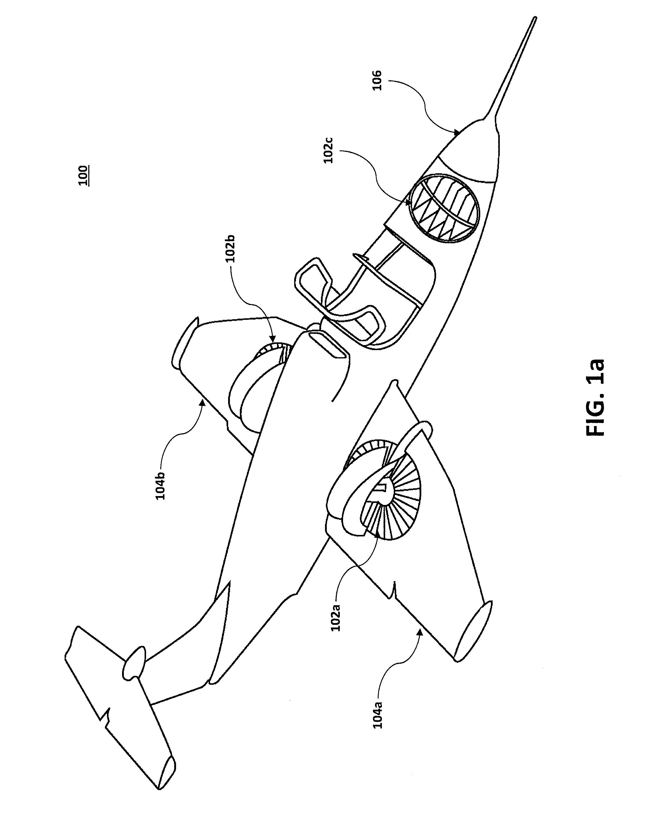
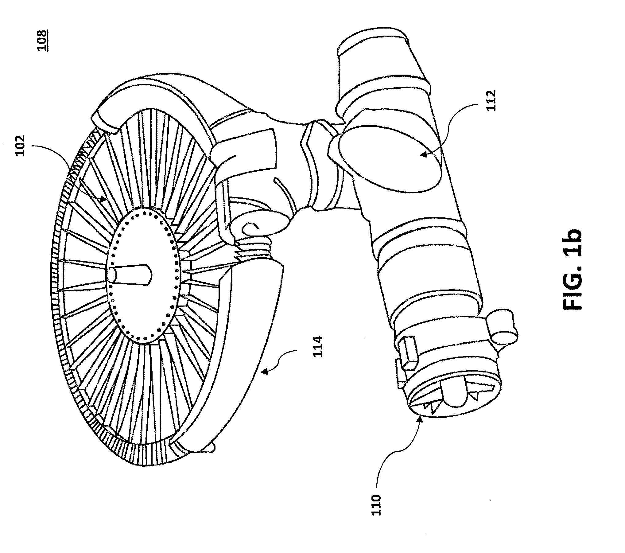
[0024]Embodiments of the present invention will be described hereinbelow with reference to the accompanying drawings. In the following description, well-known functions or constructions are not described in detail because they would obscure the invention in unnecessary detail. The present invention discloses a system and method for increasing efficiency and reducing the momentum drag of a low disc loading lift-fan aircraft, such that its peak power requirements are not greatly increased from its hover power requirements.

[0025]Lift fans are commonly used in VTOL aircraft, which can include both fixed-wing aircraft and non-fixed-wing aircraft. However, lift fans can enable VTOL aircraft to operate in other modes as well, including, for example, CTOL (conventional takeoff and landing), STOL (short takeoff and landing), and / or STOVL (short takeoff and vertical landing). Presently, there are two types of VTOL aircraft in military service: those using a tiltrotor, such as the Bell Boeing ...


PUM


Abstract

A system and method enabled to increase efficiency during a VTOL aircraft's transition. A VTOL aircraft enabled to operate multiple lift fans arranged into separately controllable groups, wherein the VTOL aircraft initially has vertical flight but transitions to horizontal flight. A first group of lift fans may be kept at full throttle, a second group of lift fans may be throttled to balance thrust and/or weight, and a third group of lift fans may be shut off.

Description

TECHNICAL FIELD[0001]The present invention relates to a system and method for use with a lift-fan aircraft. Specifically, the present invention relates to a system and method for reducing power consumption and momentum drag in a lift-fan aircraft.BACKGROUND[0002]Over the years, gas turbine-powered aircraft have used a variety of configurations in achieving vertical or short takeoffs and landings. One method is to vector the engine exhaust from one or more turbojet engines downward to create lift. Once airborne, this type of aircraft gradually transitions the thrust aft until a forward airspeed sufficient to support the aircraft is reached, at which point the aircraft is wing-borne and conventional aerodynamics may take over. Other configurations use remotely located lifting fans powered by compressor stage bleed air from the turbojet engines to create lift. Alternatively, a ducted mixture of compressor bleed air and turbojet exhaust gas may be ducted to remotely located nozzles that...

Claims


Application Information

Patent Timeline
IPC IPC(8): B64C29/00
CPCG05D1/102B64C29/0083B64C29/0025B64C11/30B64C29/0016B64C29/0091B64D27/24
Inventor PARKS, ROBERT
Owner AURORA FLIGHT SCI CORP
Why Eureka
Try Eureka