
Rotary valve adapter assembly with planetary gear system

Inactive Publication Date: 2013-06-06
BIG HORN VALVE INC
View PDF9 Cites 9 Cited by
  • Summary
  • Abstract
  • Description
  • Claims
  • Application Information

AI Technical Summary

Benefits of technology

The present invention is a rotary valve adapter assembly that includes an adapter plate, a torque multiplier assembly, a magnetic actuator assembly, and a shaft. The magnetic actuator assembly interfaces with the torque multiplier assembly and causes the sun gear to rotate when the magnets of the actuator assembly rotate. The shaft is connected to the carrier of the first planetary gear subassembly and causes the valve to open and close when the carrier rotates. The invention also includes a top enclosure and a driver housing containing the actuator assembly, and a driver cap that is affixed to the driver housing. The magnetic actuator assembly is powered by a motor and the invention is suitable for use in a variety of applications such as valve control in industrial and manufacturing processes.

Problems solved by technology

The problem with the various magnetic actuators proposed is that the amount of force transmitted by the magnets is not adequate to ensure the proper function of the valve.
If an actuator is designed to provide adequate force to open and close the valve, the magnet coupling is so large as to make it impractical.
Even with the use of modern rare-earth magnets such as Neodymium-Iron-Boron and Samarium-Cobalt, the ability to transmit, adequate force to the valve stem is still difficult.
This does not give the valve operator the confidence that his valve can be opened or closed under situations where high force is required, such as high fluid pressure, dry seals, or debris in the fluid path.
Magnetic actuation is no longer appropriate for light applications only.
At the very least, leakage from stem packings results in the loss of product, which can be costly.
The threat posed to the environment by leaking valve sterns is great, particularly when the product that is leaked is a fugitive emission, that is, a leaked or spilled product that cannot be collected back from the environment.
Personnel who are required to work near hazardous chemicals—such as operators in a petrochemical plant—are subject to injury from leaking valve stems, especially from reciprocating stems where the hazardous material inside the valve is transported to the outside environment via the stem as it retracts from the valve body.
This acid corrodes the stem, which makes it even more difficult to seal as time goes by.

Method used


Image

  • Rotary valve adapter assembly with planetary gear system
  • Rotary valve adapter assembly with planetary gear system
  • Rotary valve adapter assembly with planetary gear system

Examples


Embodiment Construction

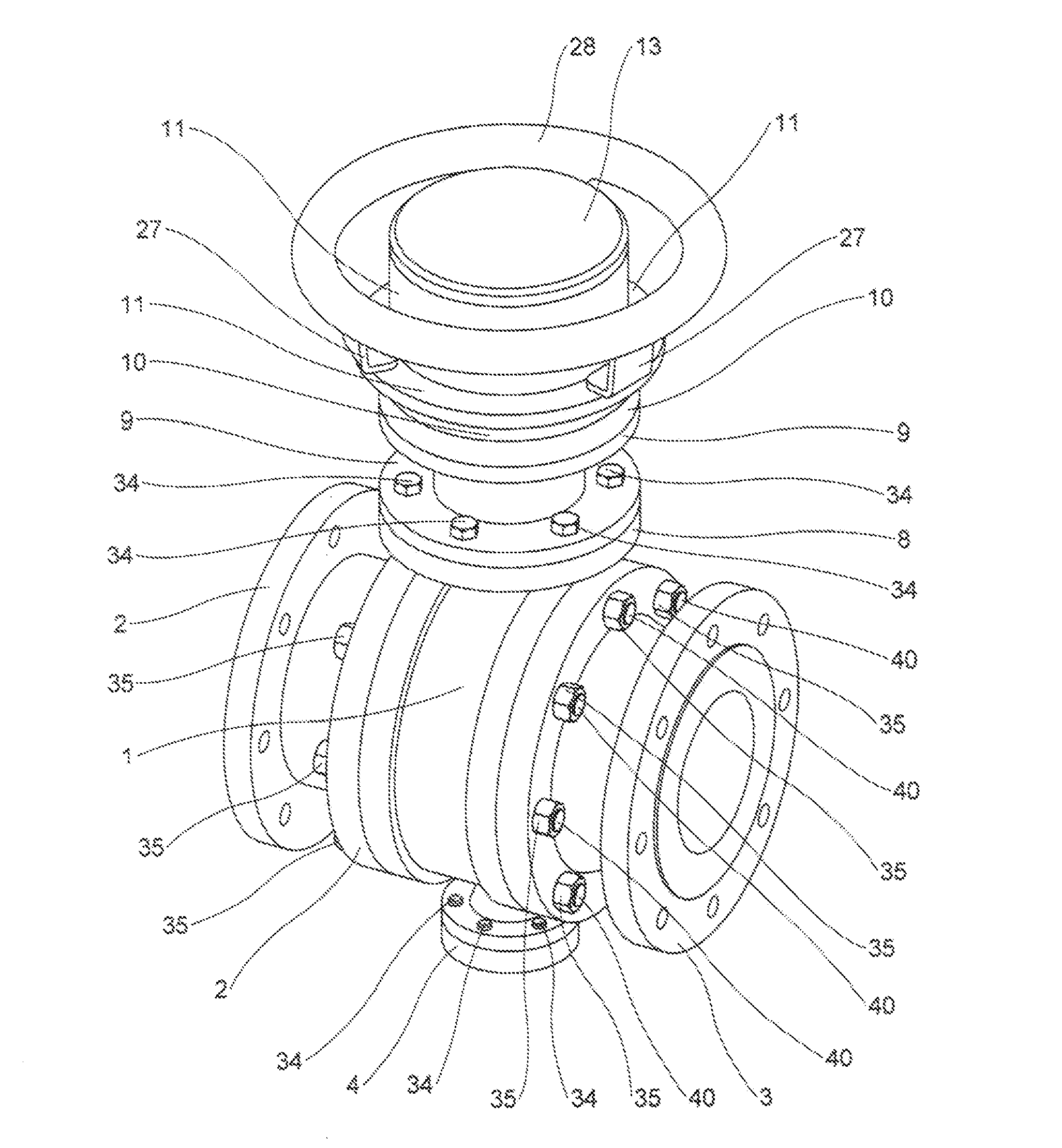
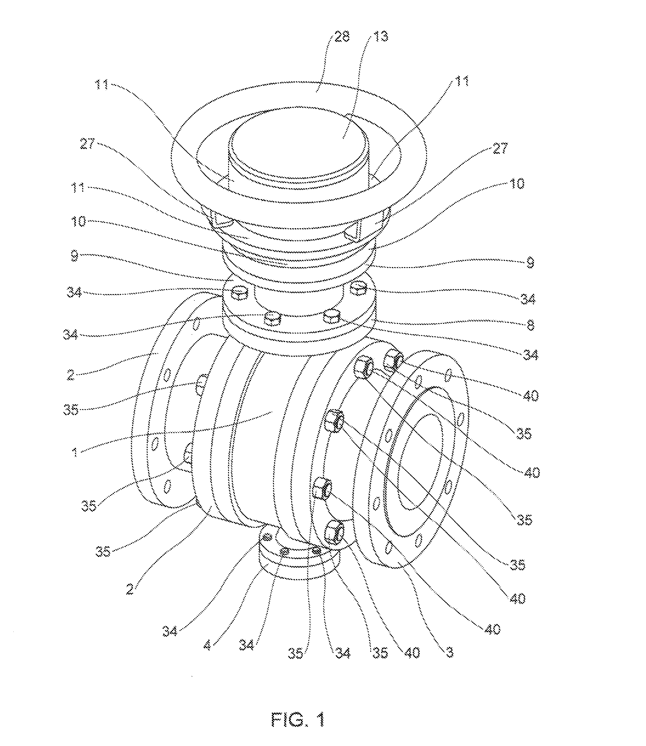
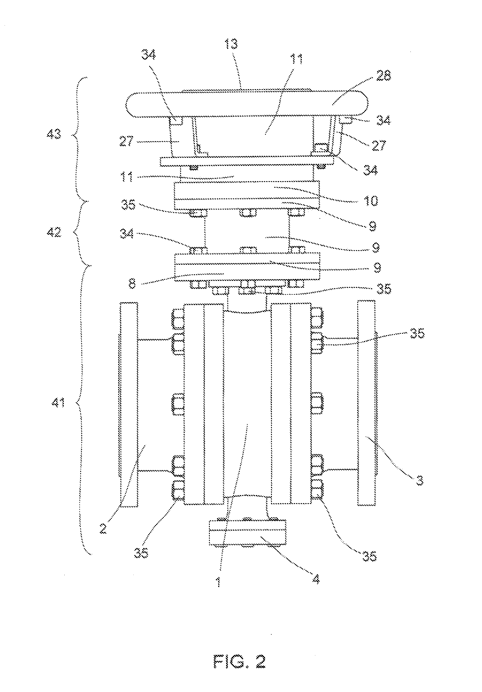
[0164]FIG. 1 is a perspective view of the present invention in a fully assembled state. This figure shows the valve body 1, the left flange 2, the right flange 3, and the trunnion cover 4. The left and right flanges 2, 3 are bolted to the valve body 1 and allow the valve to be connected to piping (not shown). The trunnion cover 4 houses the trunnion 7 (not shown). The present invention comprises an adapter plate 8, which is bolted to the bottom enclosure 9, as well as the valve body 1 (see FIG. 2). Note that the adapter plate 8 may also be integral with (i.e., the same part as) the bottom enclosure 9 rather than a separate part. As shown in subsequent figures, the bottom enclosure 9 contains the planetary gear subassemblies 44.

[0165]The bottom enclosure 9 in turn is bolted to the top enclosure 10, which contains part of the cylindrical magnet wheel actuator assembly 43 (not shown). In an alternate embodiment, the bottom and top enclosures 9, 10 are a single part. The top enclosure 1...


PUM


Abstract

A rotary valve adapter assembly comprising an adapter plate configured to attach to a rotary valve body, a torque multiplier assembly comprising one or more planetary gear subassemblies, each of which comprises a sun gear, ring gear, and a plurality of planetary gears, a magnetic actuator assembly comprising two sets of magnetically coupled magnets, and a shaft. The magnetic actuator assembly interfaces with the torque multiplier assembly such that when the magnets of the magnetic actuator assembly rotate, they cause the sun gear of a first planetary gear subassembly to rotate and the planetary gears to walk on the ring gear. The shaft interfaces with the carrier of one of the planetary gear subassemblies such that when the carrier rotates, the shaft also rotates, thereby causing the valve to open and close. The assembly further comprises a pressure equalization system comprising a piston and piston spring or spring washer stack.

Description

CROSS-REFERENCE TO RELATED APPLICATION[0001]This application is a continuation-in-part of U.S. patent application Ser. No. 13 / 310,733 filed on Dec. 3, 2011.BACKGROUND OF THE INVENTION[0002]1. Field of the Invention[0003]The present invention relates generally to the field of valves and, more specifically, to a rotary valve adapter assembly with a planetary gear system.[0004]2. Description of the Related Art[0005]A number of patent applications have been filed for valve actuators that mitigate stem leakage through the use of a magnetic interlock. These actuator chambers either enclose the dynamic seal that is present in every valve around the stem of the valves, or they eliminate the need for the seal entirely. This dynamic seal is known as a packing or mechanical seal. The magnetic interlock is employed to transmit force from outside of the actuator chamber to the inside, thus avoiding the penetration of the chamber wall by a mechanical stem actuator. Penetration of the chamber wall...

Claims


Application Information

Patent Timeline
IPC IPC(8): F16K31/08F16K31/53
CPCF16K31/088F16K31/043F16K31/055F16K31/535
Inventor BURGESS, KEVINYAKOS, DAVIDWALTHALL, BRYAN
Owner BIG HORN VALVE INC
Learn More