Multi-layer acoustic treatment panel

a multi-layer acoustic treatment and treatment panel technology, applied in the direction of machines/engines, liquid fuel engines, instruments, etc., can solve the problems that the acoustic treatment panel cannot meet these two requirements, and achieve the effect of increasing the effectiveness of acoustic treatmen

Active Publication Date: 2013-06-06
SN DETUDE & DE CONSTR DE MOTEURS DAVIATION S N E C M A +2
View PDF6 Cites 33 Cited by
  • Summary
  • Abstract
  • Description
  • Claims
  • Application Information

AI Technical Summary

Benefits of technology

[0006]A main object of the present invention is thus to mitigate such drawbacks by proposing to increase the effectiveness of acoustic treatments for a given treated surface area by acting on the characteristics of the sound source.
[0008]The presence of high-porosity zones in the perforated skin of the panel serves to create a large impedance discontinuity over a small area, thereby causing some of the energy of the low order acoustic modes to transfer to high-order acoustic modes, which are easier to attenuate acoustically. In addition to this effect of converting acoustic modes, in particular for broadband noise, because the panel of the invention has soundwave flow channels it also modifies the path of a fraction of the soundwave captured through the inlet zones in order to reinject it in phase opposition via outlet zones further downstream. This serves to enhance the attenuation of troublesome frequencies corresponding to the operating ranges of the turbojet. Thus, for given surface area, it is possible to increase considerably the effectiveness of the acoustic treatment panel.

Problems solved by technology

Unfortunately, presently-used acoustic treatment panels do not enable these two requirements to be satisfied.

Method used


Image

  • Multi-layer acoustic treatment panel
  • Multi-layer acoustic treatment panel
  • Multi-layer acoustic treatment panel

Examples


first embodiment

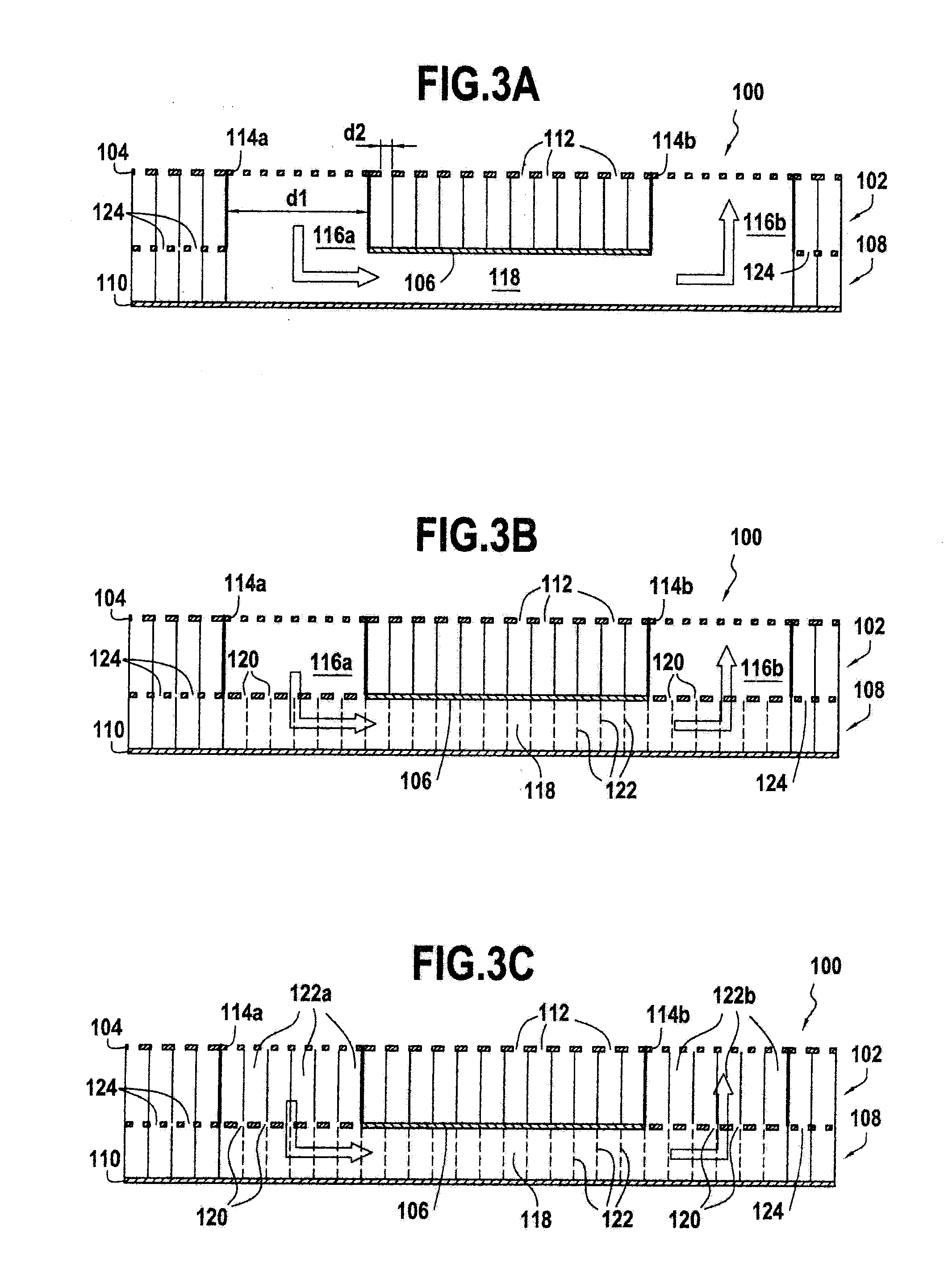
[0037]Other variants may be envisaged. In a first embodiment shown in FIG. 3A, the high-porosity zones 114a and 114b of a given pair communicate with the soundwave flow channel 118 via wells 116a and 116b passing both through the first cellular-structure core 102 and the intermediate skin 106.

second embodiment

[0038]In a second embodiment shown in FIG. 3B, the high-porosity zones 114a and 114b of a given pair communicate with the soundwave flow channel 118 via wells 116a and 116b passing through the first cellular-structure core 102 and through a plurality of orifices 120 formed through the intermediate skin 106 in register with the wells.

third embodiment

[0039]In a third embodiment shown in FIG. 3C, the high-porosity zones 114a and 114b of a given pair communicate with the soundwave flow channel 118 via passages 122a and 122b formed between the cavities in the first cellular-structure core 102 and a plurality of orifices 120 formed through the intermediate skin 106 in register with the passages 122a and 122b.

[0040]It should be observed that the intermediate skin 116 of the acoustic treatment panel of the invention is perforated by a plurality of orifices 124 with the exception of the zones covering the soundwave flow channel 118 that is arranged in the second cellular structure 108 (in other words, the zones of the intermediate skin overlying the soundwave flow channel are continuous). In these unperforated zones, the acoustic panel thus acts as a simple resonator with a porous layer beside the flow passage (i.e. the perforated wall 104) and an unperforated layer at the end of the cavity (i.e. the intermediate wall 106). In the per...


PUM


Abstract

A multilayer acoustic treatment panel including a first cellular-structure core sandwiched between a perforated skin and an intermediate skin; and a second cellular-structure core sandwiched between the intermediate skin and a continuous skin. The perforated skin includes at least one pair of high-porosity zones presenting a perforation ratio greater than a perforation ratio of a remainder of the perforated skin and including an inlet zone and an outlet zone longitudinally spaced apart from each other, the high-porosity zones of a given pair communicating through the first cellular-structure core and the intermediate skin with the two ends of a soundwave flow channel arranged in the second cellular-structure core.

Description

BACKGROUND OF THE INVENTION[0001]The present invention relates to the general field of so-called “passive” acoustic treatment.[0002]The application domain of the invention is particularly, but not exclusively, that of aviation turbine engines.[0003]The use of passive acoustic treatment panels is frequent in the field of aviation in order to reduce the emission of sound from turbine engines. For example, with a two-spool bypass type turbojet, such panels may be arranged on the inside face of the nacelle that surrounds the turbojet, and also on the outside face of its primary cover.[0004]A passive acoustic treatment panel is generally constituted by a honeycomb cellular structure covered by a thin porous layer acting as a wall for a gas flow passage and closed on its other side by a layer that is reflective from an acoustic point of view (also referred to as a continuous skin). More complex panels with intermediate porous layers inserted between honeycomb structure layers may be provi...

Claims


Application Information

Patent Timeline
Patent Type & Authority Applications(United States)
IPC IPC(8): F02C7/24
CPCF02C7/24G10K11/168F02K1/827B64D33/06G10K11/175F05D2250/32F05D2250/60F05D2250/283F05D2260/96
Inventor JULLIARD, JACQUES MICHEL ALBERTMARDJONO, JACKY NOVIRIOU, GEORGES JEAN XAVIERPOIRIER, BENJAMIN ANDRE FRANCOISVILLE, JEAN-MICHEL JEAN-FRANCOIS
Owner SN DETUDE & DE CONSTR DE MOTEURS DAVIATION S N E C M A
Why Eureka
Try Eureka