
System and method for memory storage

Active Publication Date: 2013-06-06
IND TECH RES INST
View PDF6 Cites 65 Cited by
  • Summary
  • Abstract
  • Description
  • Claims
  • Application Information

AI Technical Summary

Benefits of technology

The patent is about a memory storage system and management method that can efficiently control multiple flash memory devices. It uses a central control device and management method to handle mapping between logical and physical addresses. The system also has a power-failure recovery method that can quickly recover lost information from the flash memory devices. The technical effects of this patent system and method include improved efficiency in managing flash memory devices and faster recovery of lost information due to power-failure.

Problems solved by technology

In more details, although the access speed of a flash memory is not so fast as a dynamic random-access memory (DRAM), but it is low noise, small volume and fast access.
When the erasing number of times of a physical block reaches the upper limit, the physical block may be damaged and unable to write date into.
Based on the above mentioned description, in a large server, if the system employs flash memories serving as storage units, many problems must be confronted.
For example, a plurality of flash memory storage devices must be managed simultaneously, so that the translation management between logical positions and physical positions becomes more complex.
Since during the operation of the flash memory storage system, the BMT must be temporally stored in a volatile memory for updating convenience, hence, once abnormal shutdown occurs, the BMT would be lost.
When that is the case, although the BMT can be rebuilt by scanning the spare-areas of the physical pages of all the physical blocks in all the flash memory storage devices during rebooting, but it definitely consumes much time.

Method used


Image

  • System and method for memory storage
  • System and method for memory storage
  • System and method for memory storage

Examples


Embodiment Construction

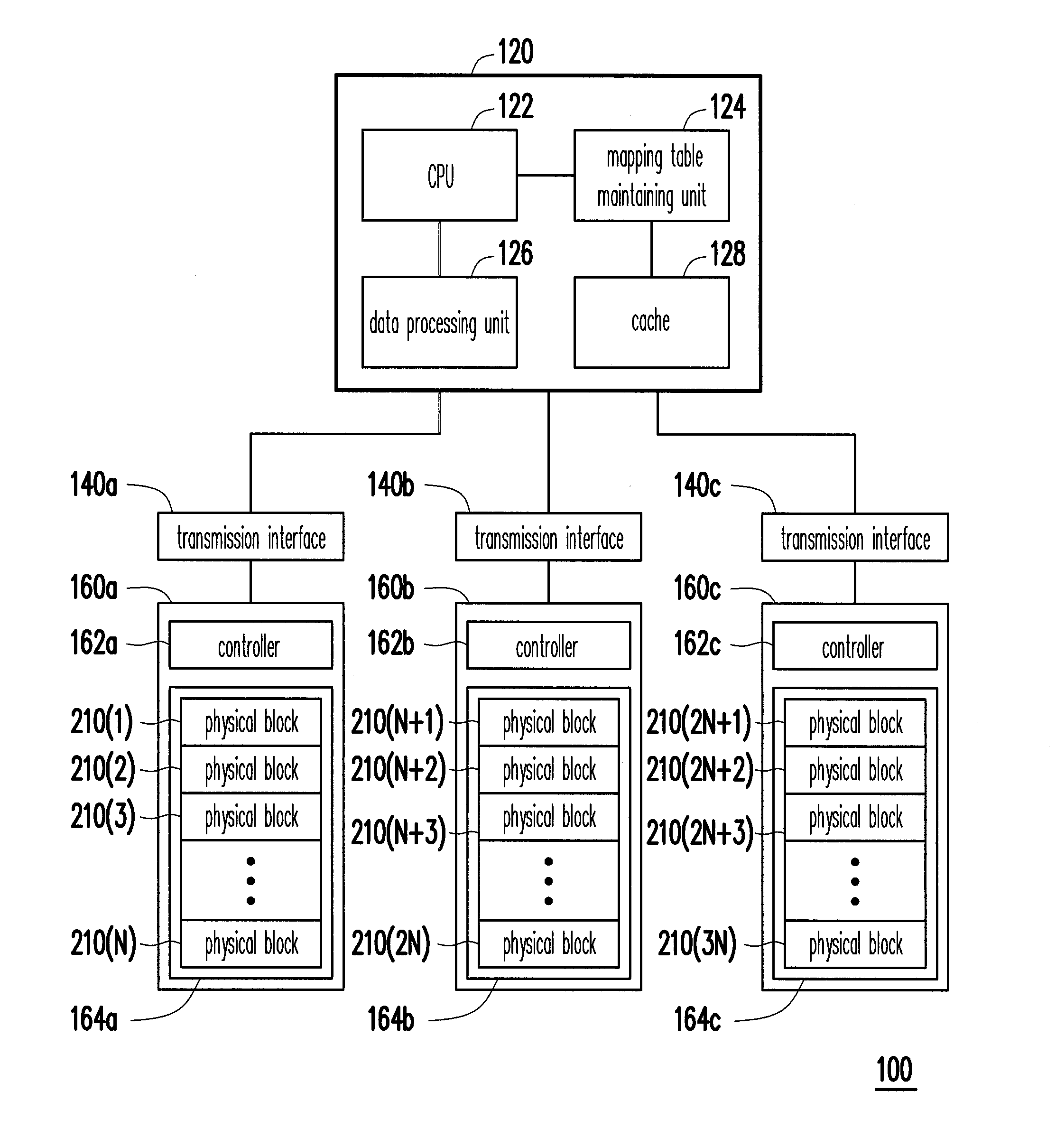
[0027]FIG. 1 is a block diagram of a memory storage system according to an exemplary embodiment of the disclosure.

[0028]Referring to FIG. 1, a memory storage system 100 includes a central control device 120, a plurality of transmission interfaces (i.e., a first transmission interface 140a, a second transmission interface 140b and a third transmission interface 140c) and a plurality of flash memory storage devices (i.e., a first flash memory storage device 160a, a second flash memory storage device 160b and a third flash memory storage device 160c).

[0029]The central control device 120 is respectively coupled to the first flash memory storage device 160a, the second flash memory storage device 160b and the third flash memory storage device 160c through the first transmission interface 140a, the second transmission interface 140b and the third transmission interface 140c for controlling and managing the first flash memory storage device 160a, the second flash memory storage device 160b...


PUM


Abstract

A memory storage system includes multiple flash memory storage devices, multiple transmission interfaces and a central control device. The central control device has a cache and respectively coupled to the flash memory storage devices through the transmission interfaces. The central control device is for maintaining a block map table (BMT) to record a mapping relationship between multiple logical blocks and the physical blocks of the flash memory storage devices and the BMT is temporarily stored in the cache. In addition, the central control device uses the communication commands to access the physical blocks of the flash memory storage devices, in which the communication commands are transmitted to multiple controllers in the flash memory storage devices through the transmission interfaces and the controllers access the physical blocks according to communication commands. In this way, the system can effectively manage multiple flash memory storage devices.

Description

BACKGROUND OF THE INVENTION[0001]1. Field of the Invention[0002]The disclosure relates to a memory storage system and a central control device, a management method and a power-failure recovery method.[0003]2. Description of the Related Art[0004]The flash memory is a non-volatile storage device. The data stored in a flash memory would not disappear during power-off and the flash memory is able to provide fast reading efficiency. In more details, although the access speed of a flash memory is not so fast as a dynamic random-access memory (DRAM), but it is low noise, small volume and fast access. In electronic communication products, the flash memory thereby has been broadly applied in commodity such as camera, mobile phone, flash drive and notebook computer.[0005]A flash memory has unique characteristic. For example, data can not be directly repeatedly written into the same physical address; instead, the data only can be rewritten after performing an erasing operation. In addition, a ...

Claims


Application Information

Patent Timeline
IPC IPC(8): G06F12/00
CPCG06F11/1417G06F2212/7201G06F12/0875G06F12/0246
Inventor CHIUEH, TZI-CKERCHIEN, TING-FANGTSAO, SHIH-CHIANGLEE, CHIEN-YUNG
Owner IND TECH RES INST
Features
  • Generate Ideas
  • Intellectual Property
  • Life Sciences
  • Materials
  • Tech Scout
  • Unparalleled Data Quality
  • Higher Quality Content
  • 60% Fewer Hallucinations
Learn More